Chrysler New Yorker. Manual - part 265


  Index      Chrysler     Chrysler New Yorker - service repair manual 1997-1999 year


Search            


Content   ..  263  264  265  266   ..


Chrysler New Yorker. Manual - part 265


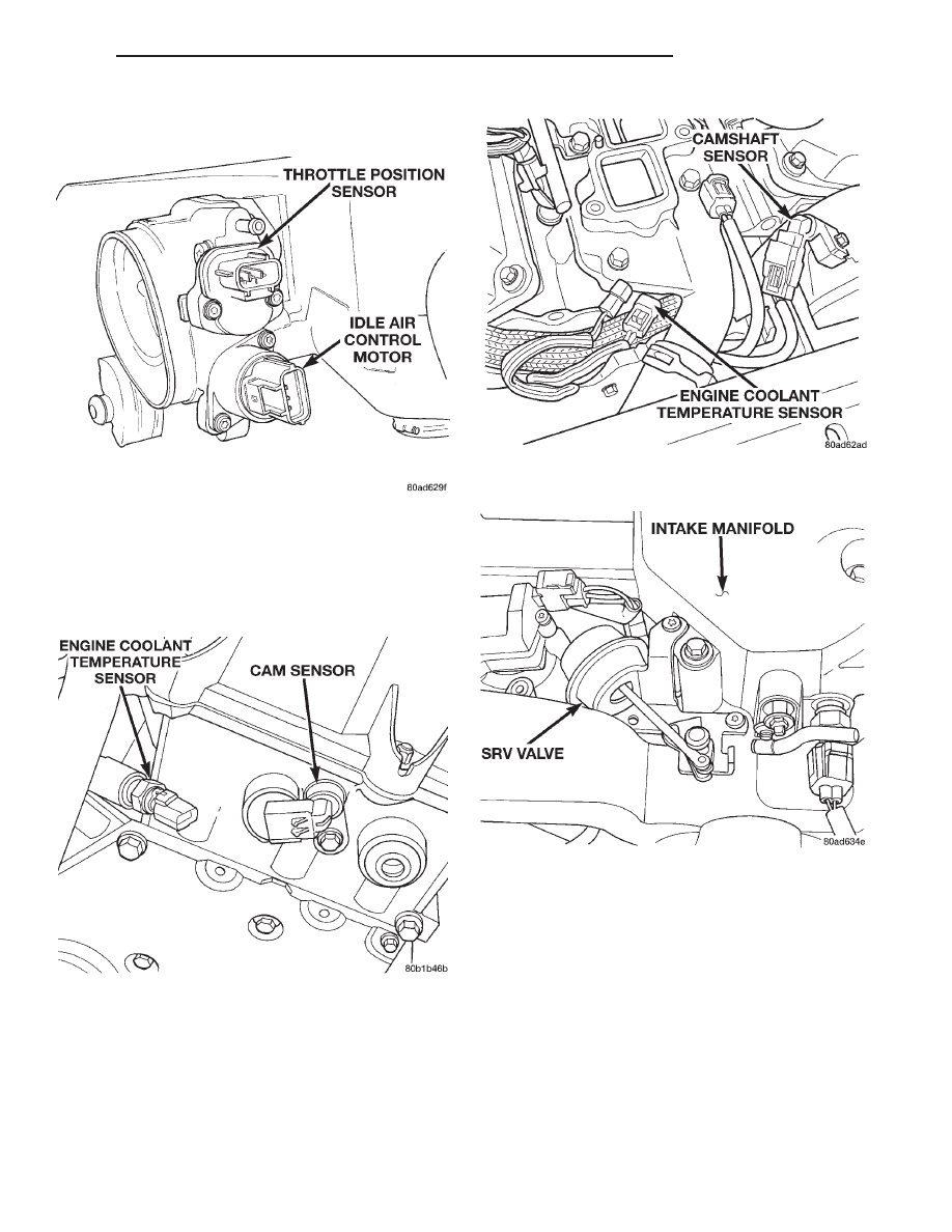
(4) Ensure the electrical connector is completely

attached to the idle air contact motor (Fig. 32).

(5) Ensure electrical connector is attached to the

throttle position sensor (Fig. 32).

(6) Verify the electrical connector is attached to

the engine coolant temperature sensor (Fig. 33) or
(Fig. 34).

(7) Ensure purge hose is connected to throttle

body.

(8) Ensure the vacuum hose is connected to the

Short Runner valve and the vacuum harness (Fig.
35).

(9) Ensure the Proportional Purge solenoid (Fig.

36) electrical connectors are attached to the solenoid.

(10) Inspect the air cleaner filter element. Replace

as necessary.

(11) Verify the 2 40-way connector is fully inserted

into the Powertrain Control Module (PCM) (Fig. 39).
Ensure the wires are not stretched or pulled out of
the socket.

Fig. 32 Idle Air Control Motor—2.7L Engine

Fig. 33 Engine Coolant Temperature Sensor—2.7L

Engine

Fig. 34 Engine Coolant Temperature Sensor—3.2/

3.5L Engine

Fig. 35 Short Runner Valve

300M

FUEL SYSTEM

14 - 35

DIAGNOSIS AND TESTING (Continued)

Fig. 36 Proportional Purge Solenoid

Fig. 37 Air Cleaner Housing

Fig. 38 Air Cleaner Element

Fig. 39 PCM Connectors

14 - 36

FUEL SYSTEM

300M

DIAGNOSIS AND TESTING (Continued)

(12) Ensure the accessory drive belt tension is cor-

rect.

(13) Check for loose or corroded connections at the

generator (Fig. 40).

(14) Check fuel supply tube connections for leaks.
(15) Verify electrical connector is attached to the

crankshaft position sensor (Fig. 41).

(16) Ensure the electrical connectors are attached

to the upstream heated oxygen sensors (Fig. 42) or
(Fig. 43).

Fig. 40 Generator

Fig. 41 Crankshaft Position Sensor

Fig. 42 Upstream Heated Oxygen Sensor

Fig. 43 Upstream Heated Oxygen Sensor

300M

FUEL SYSTEM

14 - 37

DIAGNOSIS AND TESTING (Continued)

(17) Ensure the electrical connectors are attached

to the downstream heated oxygen sensors(Fig. 44).

(18) Check for loose or corroded electrical connec-

tions at the starter motor (Fig. 45).

ASD AND FUEL PUMP RELAYS

The following description of operation and

tests apply only to the Automatic Shutdown
(ASD) and fuel pump relays
. The terminals on the
bottom of each relay are numbered (Fig. 46) or (Fig.
47).

OPERATION

• Terminal number 30 is connected to battery volt-

age. For both the ASD and fuel pump relays, termi-
nal 30 is connected to battery voltage at all times.

• The PCM grounds the coil side of the relay

through terminal number 85.

• Terminal number 86 supplies voltage to the coil

side of the relay.

• When the PCM de-energizes the ASD and fuel

pump relays, terminal number 87A connects to termi-
nal 30. This is the Off position. In the off position,
voltage is not supplied to the rest of the circuit. Ter-
minal 87A is the center terminal on the relay.

• When the PCM energizes the ASD and fuel

pump relays, terminal 87 connects to terminal 30.
This is the On position. Terminal 87 supplies voltage
to the rest of the circuit.

TESTING

The following procedure applies to the ASD and

fuel pump relays.

(1) Remove relay from connector before testing.
(2) With the relay removed from the vehicle, use

an ohmmeter to check the resistance between termi-
nals 85 and 86. The resistance should be between 75
65 ohms.

Fig. 44 Downstream Heated Oxygen Sensors

Fig. 45 Starter Motor

Fig. 46 ASD and Fuel Pump Relay Terminals

Fig. 47 ASD and Fuel Pump Relay Terminals

14 - 38

FUEL SYSTEM

300M

DIAGNOSIS AND TESTING (Continued)


Content   ..  263  264  265  266   ..