Chrysler New Yorker. Manual - part 264


  Index      Chrysler     Chrysler New Yorker - service repair manual 1997-1999 year


Search            


Content   ..  262  263  264  265   ..


Chrysler New Yorker. Manual - part 264


MANIFOLD TUNING VALVE (MTV)—PCM OUTPUT

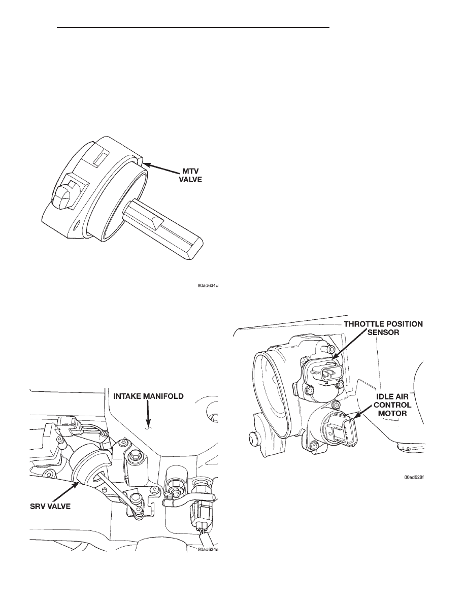
The PCM controls the MTV solenoid. The manifold

tuning valve optimizes acoustical tuning of the
intake system during wide open throttle operation
throughout the RPM range. The valve opens a cross-
over passage in that connects both sides of the intake
manifold plenum (Fig. 22).

SHORT RUNNER VALVE (SRV)

The SRV system operates under WOT conditions

above 5000 rpm to maximize engine performance.
When actuated by the PCM, the SRV solenoid ener-
gizes, allowing mechanical linkage to redirect the
intake air flow to six short runners. The PCM looks
for a current spike when actuating the solenoid. If
the spike is not present, the PCM sets the DTC.

GENERATOR FIELD—PCM OUTPUT

The PCM regulates the charging system voltage

within a range of 12.9 to 15.0 volts. Refer to Group
8A for Battery system information and 8C for charg-
ing system information.

IDLE AIR CONTROL MOTOR—PCM OUTPUT

The idle air control motor attaches to the throttle

body (Fig. 24). The PCM operates the idle air control
motor. The PCM adjusts engine idle speed through
the idle air control motor to compensate for engine
load or ambient conditions.

The throttle body has an air bypass passage that

provides air for the engine at idle (the throttle blade
is closed). The idle air control motor pintle protrudes
into the air bypass passage and regulates air flow
through it.

The PCM adjusts engine idle speed by moving the

idle air control motor pintle in and out of the bypass
passage. The adjustments are based on inputs the
PCM receives. The inputs effecting idle speed include
the throttle position sensor, road speed (from Trans-
mission Control Module), coolant temperature sensor,
battery voltage and battery temperature. Also vari-
ous switch operations (brake, park/neutral, air condi-
tioning)

effect

idle

speed.

The

PCM

prevents

deceleration die out by increasing air flow when the
throttle closes quickly.

Fig. 22 Manifold Tuning Valve

Fig. 23 Short Runner Valve (SRV)

Fig. 24 Idle Air Control Motor

300M

FUEL SYSTEM

14 - 31

DESCRIPTION AND OPERATION (Continued)

DATA LINK CONNECTOR—PCM OUTPUT

The data link connector (diagnostic connector)

links the DRB scan tool with the Powertrain Control
Module (PCM). Refer to On-Board Diagnostics in the
General Diagnosis section of this group. The data
link connector is located inside the vehicle, below
instrument panel next to the center column (Fig. 25).

FUEL INJECTORS—PCM OUTPUT

The engines uses top feed injectors (Fig. 26).
The Automatic Shut Down (ASD) relay supplies

battery voltage to the injectors. The PCM controls
the ground path for each injector in sequence. By
switching the ground paths on and off, the PCM fine-
tunes injector pulse width. Injector pulse width
refers to the amount of time an injector operates.

The PCM determines injector synchronization from

the camshaft position sensor and crankshaft position
sensor inputs. The PCM grounds the ASD and fuel
pump relays after receiving the camshaft position
sensor and crankshaft position sensor inputs.

The PCM energizes the injectors in a sequential

order during all engine operating conditions except
start-up. During start-up, when the coolant tempera-
ture is below 15° C (60° F), all injectors are energized
at the same time. Above 15° C, the PCM energizes
the injectors in sequence. Once the PCM determines
crankshaft position, it begins energizing the injectors
in sequence.

IGNITION COIL—PCM OUTPUT

The PCM determines which of the coils to charge

and fire at the correct time. The Automatic Shut
Down (ASD) relay provides battery voltage to the
ignition coil. The PCM provides a ground contact (cir-
cuit) for energizing the coil. When the PCM breaks
the contact, the energy in the coil primary transfers
to the secondary causing the spark. The PCM will de-
energize the ASD relay if it does not receive the
crankshaft sensor and camshaft sensor inputs. Refer
to Automatic Shut Down (ASD) Relay and Fuel
Pump Relay—PCM in this section for relay opera-
tion.

Fig. 25 Data Link Connector

Fig. 26 Fuel Injector

Fig. 27 Ignition Coil 2.7L Engine

14 - 32

FUEL SYSTEM

300M

DESCRIPTION AND OPERATION (Continued)

MALFUNCTION INDICATOR (CHECK ENGINE)
LAMP—PCM OUTPUT

The PCM supplies the malfunction indicator (check

engine) lamp on/off signal to the instrument panel
through the PCI Bus. The PCI Bus is a communica-
tions port. Various modules use the PCI Bus to
exchange information.

The Check Engine lamp comes on each time the

ignition key is turned ON and stays on for 3 seconds
as a bulb test.

The Malfunction Indicator Lamp (MIL) stays on

continuously, when the PCM has entered a Limp-In
mode or identified a failed emission component. Dur-
ing Limp-in Mode, the PCM attempts to keep the
system operational. The MIL signals the need for
immediate service. In limp-in mode, the PCM com-
pensates for the failure of certain components that
send incorrect signals. The PCM substitutes for the
incorrect signals with inputs from other sensors.

If the PCM detects active engine misfire severe

enough to cause catalyst damage, it flashes the MIL.
At the same time the PCM also sets a Diagnostic
Trouble Code (DTC).

For signals that can trigger the MIL (Check

Engine Lamp) refer to Group 25, On-Board
Diagnostics.

RADIATOR FAN RELAYS—PCM OUTPUT

The cooling system uses two fans. Both fans oper-

ate at two different speeds, low and high. Depending
on engine coolant temperature and A/C system high
side pressure, the both fans operate at either low or
high. The PCM controls radiator speed by grounding
the coil side of either the low speed fan relay or the
high speed fan relay. The ignition switch supplies
voltage to the coil sides of the relay. When the PCM
grounds the coil side of the relay, the contacts close
and the battery supplies power to the fans.

The low speed and high speed fan relays are

located in the Power Distribution Center (PDC) near
the battery. A decal on the inside of the PDC covers
shows the locations of each relay and fuse contained
in the PDC.

SPEED CONTROL SERVOS—PCM OUTPUT

The PCM controls operation of the vacuum and

vent solenoids inside the speed control servo. When
the operator presses the on switch, the PCM provides
power through the brake switch to the servo. When
the speed control system is engaged following a set or
resume, the PCM supplies a ground to the vacuum
and or vent solenoids inside the servo as needed to
maintain the selected vehicle speed. Refer to Group
8H, Speed Control for more information.

TACHOMETER—PCM OUTPUT

The tachometer receives its information across the

PCI Bus from the Body Control Module (BCM). Infor-
mation on engine RPM is transmitted from the Pow-
ertrain Control Module (PCM) across the PCI Bus to
the BCM. The BCM calculates the position of the
tachometer pointer based on the input from the PCM
and adjusts the position of the gauge pointer to the
necessary position. This signal is sent over the PCI
Bus to the instrument cluster.

TORQUE MANAGEMENT

The PCM receives the torque management input

from the transmission control module. The PCM
receives the input when the transmission shifts
gears. In response, the PCM shuts off a number of
fuel injectors when the transmission shifts gears.

Fig. 28 Ignition Coil 3.2/3.5L Engine

300M

FUEL SYSTEM

14 - 33

DESCRIPTION AND OPERATION (Continued)

5 VOLT SUPPLY—PCM OUTPUT

The PCM supplies 5 volts to the following sensors:
• A/C pressure transducer

• Engine coolant temperature sensor

• Manifold absolute pressure sensor

• Throttle position sensor

• Linear EGR solenoid

8-VOLT SUPPLY—PCM OUTPUT

The PCM supplies 8 volts to the crankshaft posi-

tion sensor, camshaft position sensor.

DIAGNOSIS AND TESTING

VISUAL INSPECTION

Before diagnosing or servicing the fuel injection

system, perform a visual inspection for loose, discon-
nected, or misrouted wires and hoses. A thorough
visual inspection that includes the following checks
saves unnecessary test and diagnostic time.

(1) Remove the Power Distribution Center (PDC)

cover. Check for blown fuses. Ensure all relays are
properly installed (Fig. 29).

(2) Check the battery terminal connections for

loose cables and corrosion.

(3) Check the MAP sensor electrical connection

(Fig. 30) or (Fig. 31).

Fig. 29 Power Distribution Center

Fig. 30 MAP Sensor—2.7L Engine

Fig. 31 MAP Sensor—3.2/3.5L Engine

14 - 34

FUEL SYSTEM

300M

DESCRIPTION AND OPERATION (Continued)


Content   ..  262  263  264  265   ..