Chrysler New Yorker. Manual - part 66


  Index      Chrysler     Chrysler New Yorker - service repair manual 1997-1999 year


Search            


Content   ..  64  65  66  67   ..


Chrysler New Yorker. Manual - part 66


JUNCTION BLOCK/BODY CONTROL MODULE (BCM)

JUNCTION BLOCK

REMOVAL

The Junction Block and Body Control Module

(BCM) are attached to each other. After removal,
they can be separated. The Junction Block/BCM
assemblies are located on the driver’s side of the
vehicle (Fig. 8).

(1) Open hood and disconnect the negative battery

cable remote terminal from the remote battery post
(Fig. 18).

(2) Open the front driver’s door and remove left

end cap.

(3) Remove two screws from lower instrument panel

cover (outside end). Pull rearward on lower instru-
ment panel cover releasing clips. Disconnect decklid
release switch wiring and remove cover from vehicle.

(4) Remove wire harness connectors from Junction

Block/BCM.

(5) Remove Junction Block/BCM three mounting

screws.

(6) Remove

Junction

Block/BCM

by

pulling

straight down from the mounting bayonet.

(7) Disconnect BCM wire connectors and RKE

antenna connector.

(8) Remove Junction Block/BCM from vehicle.

INSTALLATION

For installation, reverse the above procedures.

Ensure that the wire terminals and connectors are in
good condition and connectors are properly installed.

BODY CONTROL MODULE (BCM)

REMOVAL

(1) With the Junction Block/BCM removed from the

vehicle, separate the BCM from the Junction Block.

(2) Remove the four BCM attaching screws from

the Junction Block.

(3)

Disconnect BCM from the Junction Block.

NOTE: The

Remote

Keyless

Entry

module

is

attached to the BCM with three screws. This must
be transferred to the new BCM if being replaced.

INSTALLATION

For installation, reverse the above procedures.

OUTLET (12 VOLT) BASE

REMOVAL

(1) Open hood and disconnect the negative battery

cable remote terminal from the remote battery post
(Fig. 18).

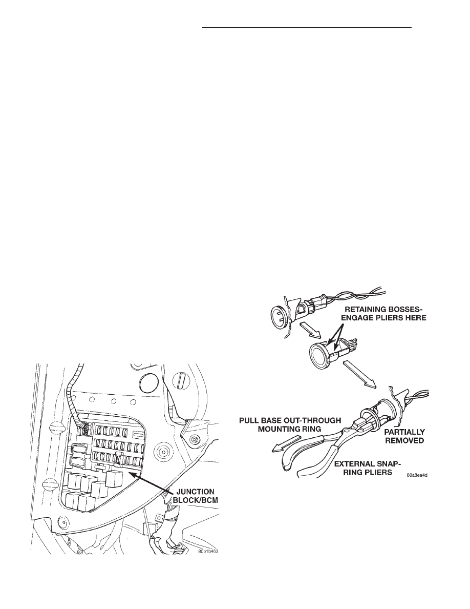
(2) Look inside and note position of the retaining

bosses (Fig. 9).

(3) Using external snap ring pliers with 90 degree

tips. Insert pliers with tips against bosses and
squeeze forcing bosses out of base.

(4) Pull out the base through mounting ring by

gently rocking pliers. A tool can be made to do the
same. Refer to (Fig. 10).

(5) Disconnect the base wires.
(6) Set base aside and remove base mount ring.

Fig. 8 Junction Block/BCM Location

Fig. 9 Outlet Base Removal

8E - 6

INSTRUMENT PANEL AND SYSTEMS

LH

REMOVAL AND INSTALLATION (Continued)

INSTALLATION

(1) Position mount ring to the instrument panel

and feed the wires through ring. Index the cap and
the mount ring with the index tab at 9 o’clock to the
key in the instrument panel. Install the ring.

(2) Connect wires to base. Orient base alignment

rib at 11 o’clock to mate the groove in mount ring at
the same location

(3) Push base into the bezel till it locks.
(4) Install cigar lighter cap and check operation of

element.

CLUSTER AND BEZEL

REMOVAL

To service any instrument cluster component, the

instrument cluster must be removed from the instru-
ment panel. Use the following procedure:

(1) Open hood and disconnect the negative battery

cable remote terminal from the remote battery post
(Fig. 18).

(2) Remove the instrument panel left end cap.
(3) Tilt the steering column down into the lowest

position.

(4) Using a trim stick (special tool #C-4755), gently

pry out on the instrument panel cluster bezel and
remove.

(5) Remove the instrument cluster screws and dis-

engage the upper latch.

CAUTION:

Tilt steering wheel down to gain access

for instrument cluster removal.

(6) Remove the instrument cluster from panel. The

instrument panel wiring harness connectors are self-
aligning, mounted directly to the rear panel. A force
of approximately 9 kilograms (20 lbs.) will be
required to disengage the cluster from the connec-
tors. In the lower corners of the cluster housing, tabs
have been provided so that a “hook” type device can
be used to aid in removal.

INSTALLATION

For installation, reverse the above procedures.

CLUSTER LAMPS

To service instrument cluster lamps, the cluster must

be removed from the instrument panel. For removal
and installation procedures of the instrument cluster
and bezel refer to the procedures in this section.

Refer to (Fig. 11) and (Fig. 12) for cluster lamp

locations.

The lamps that are replaceable are called out on

the back cover of the instrument cluster. All other
indicators are Light Emitting Diodes (LED’s), and
are serviced with the printed circuit (PC) board. If a
LED is non-functional, the entire PC board must be
replaced. Refer to the INDICATORS – BULBS table
for applications.

Fig. 10 Tool For Outlet Removal

INDICATORS – BULBS

INDICATOR

COLOR

BULB # / LED

BATTERY

RED

LED

BRAKE

RED

LED

AIRBAG

RED

LED

LOW OIL

RED

LED

SEATBELT

RED

LED

TEMPERATURE

RED

LED

DOOR AJAR

RED

LED

DECKLID AJAR

RED

LED

HIGH BEAM

BLUE

74

TURN SIGNALS

GREEN

194

CRUISE

GREEN

74

TRAC ON

GREEN

74

TRAC OFF

AMBER

LED

CHECK ENGINE

AMBER

LED

ABS

AMBER

LED

LOW FUEL

AMBER

LED

LOW WASHER
FLUID

AMBER

LED

ILLUMINATION

BLUEGREEN

194

Fig. 11 Cluster lamps – Intrepid

LH

INSTRUMENT PANEL AND SYSTEMS

8E - 7

REMOVAL AND INSTALLATION (Continued)

CLUSTER MASK/LENS

The instrument cluster must be removed for mask/

lens service. Refer to Instrument Cluster Removal
and Installation procedures.

REMOVAL

(1) Open hood and disconnect the negative battery

cable remote terminal from the remote battery post
(Fig. 18).

(2) Remove instrument cluster from vehicle. Refer

to procedures in this section.

(3) Remove two screws to mask/lens (Fig. 13).

(4) Unsnap seven retaining tabs holding mask/lens

to cluster housing (Fig. 14).

(5) Separate mask/lens from instrument cluster

and remove.

INSTALLATION

For installation, reverse the above procedures.

CLUSTER PRINTED CIRCUIT BOARD

The instrument cluster must be removed for

Printed Circuit Board service. Refer to Instrument
Cluster Removal and Installation procedures.

REMOVAL

(1) Open hood and disconnect the negative battery

cable remote terminal from the remote battery post
(Fig. 18).

(2) Remove instrument cluster from vehicle. Refer

to procedures in this section.

(3) Remove

five

cluster

back

cover

retaining

screws and remove the cover.

(4) Remove nine screws to Printed Circuit Board

and remove.

INSTALLATION

For installation, reverse the above procedures.

COMBINATION FLASHER

The combination flasher is located on the left side

of the instrument panel, underneath, between the
junction block and the brake pedal.

REMOVAL

(1) Open hood and disconnect the negative battery

cable remote terminal from the remote battery post
(Fig. 18).

NOTE: It may be necessary to remove the left side
lower instrument panel cover to gain access to
Combination Flasher.

(2) Slide the Combination Flasher rearward to

remove from the electrical bracket.

INSTALLATION

For installation, reverse the above procedures.

Fig. 12 Cluster lamps – Concorde

Fig. 13 Instrument Cluster Mask/Lens Retaining

Screws

Fig. 14 Instrument Cluster Mask/Lens Retaining

Tabs – Top

8E - 8

INSTRUMENT PANEL AND SYSTEMS

LH

REMOVAL AND INSTALLATION (Continued)

DECKLID RELEASE SWITCH

REMOVE

(1) Open hood and disconnect the negative battery

cable remote terminal from the remote battery post
(Fig. 18).

(2) Remove left instrument panel endcap. Refer to

Removal and Installation procedures in this section.

(3) Remove left lower instrument panel cover.

Refer

to

Instrument

Panel

and

Pad Assembly

Removal and Installation procedures in this section.

(4) Using a trim stick (special tool #C-4755), gently

pry switch out of lower cover and remove from panel.

INSTALLATION

For installation, reverse the above procedures.

GLOVE BOX DOOR/HANDLE

REMOVAL

(1) Remove the four screws at bottom of glove box

door.

(2) Open the glove box door and press sidewalls

inboard to remove the door/box assembly from instru-
ment panel.

(3) Place the glove box on a cloth to protect the

door surface.

(4) Remove the nine screws from backside of the

door.

(5) Separate the inner and outer door.
(6) Remove one screw to the handle and latch.
(7) Remove handle and latch from outer door.

NOTE: If the glove box door is going to be left off
for an extended period of time, the Ignition Off
Draw (IOD) fuse should be pulled to maintain bat-
tery condition.

INSTALLATION

For installation, reverse the above procedures.

GLOVE BOX LAMP/SWITCH ASSEMBLY

REMOVAL

(1) Open hood and disconnect the negative battery

cable remote terminal from the remote battery post
(Fig. 18).

(2) Open the glove box door, and pull out the glove

box lamp/switch assembly from upper right hand cor-
ner of opening (Fig. 15).

(3) Replace the lamp if necessary.
(4) To replace the lamp/switch assembly, discon-

nect the wire connector.

(5) Remove the lamp/switch assembly.

INSTALLATION

For installation, reverse the above procedures.

HEADLAMP SWITCH

REMOVAL

(1) Open hood and disconnect the negative battery

cable remote terminal from the remote battery post
(Fig. 18).

(2) Remove the left end cover and the cluster

bezel.

(3) Remove the three screws on headlamp switch.
(4) Remove headlamp switch from vehicle.

INSTALLATION

For installation, reverse the above procedures.

Twist out lamp sockets are serviceable at this time.
Ensure that the switch is seated against the pad.

HEATER–A/C CONTROLS

REMOVAL

(1) Open hood and disconnect the negative battery

cable remote terminal from the remote battery post
(Fig. 18).

(2) Remove the ash receiver assembly, if necessary.

Fig. 15 Glove Box Lamp/Switch

LH

INSTRUMENT PANEL AND SYSTEMS

8E - 9

REMOVAL AND INSTALLATION (Continued)


Content   ..  64  65  66  67   ..