Chrysler New Yorker. Manual - part 65
• Low fuel
• Seat belt
• Cruise
• Brake/park brake
• High beam
• Turn signals
• Door Ajar
• Decklid Ajar
• ABS (optional)
• Traction Control Active (optional)
• Traction Control Off (optional)
• Low Washer Fluid
The gauges are the magnetic air-core type. When
the ignition switch is OFF, the gauge pointers should
rest at or below the low graduation.
DIAGNOSIS AND TESTING
DIAGNOSTIC PROCEDURE
In order to diagnose the instrument cluster func-
tion, a scan tool (DRB) and the proper Body Diagnos-
tic Procedures Manual are required.
As a quick diagnosis, the cluster will perform a
functional check of the odometer display, transmis-
sion range display and warning indicators after the
ignition is switched to run/start. If the cluster is not
receiving any bus messages, the cluster will appear
non-functional and “no bus” will appear in the odom-
eter display.
A self-test of the cluster can also be initiated by
pressing and holding the odometer reset button and
switching the ignition from lock to unlock. The clus-
ter will then step through several displays for func-
tional verification.
If the cluster is not functioning properly, refer to
the proper Body Diagnostic Procedures Manual.
If the cluster is not receiving PCI bus messages,
refer to the pre-diagnostic test described in Body
Diagnostic Procedures Manual.
If the diagnostic procedure determines that a
replacement of an instrument cluster component is
required, refer to the Removal and Installation Pro-
cedures.
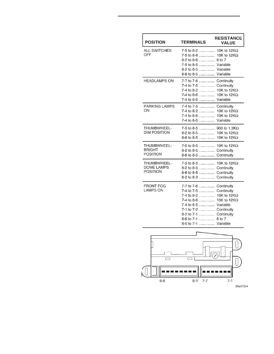
HEADLAMP SWITCH TEST
Using an ohmmeter, test for continuity between
the terminals of the switch as shown in the Head-
lamp Switch Test (Fig. 3).
Fig. 3 Headlamp Switch Test
8E - 2
INSTRUMENT PANEL AND SYSTEMS
LH
DESCRIPTION AND OPERATION (Continued)