Chrysler Crossfire. Manual - part 992


  Index      Chrysler     Chrysler Crossfire - service repair manual 2005 year


Search            


Content   ..  990  991  992  993   ..


Chrysler Crossfire. Manual - part 992


1. Connect a manifold gauge set.

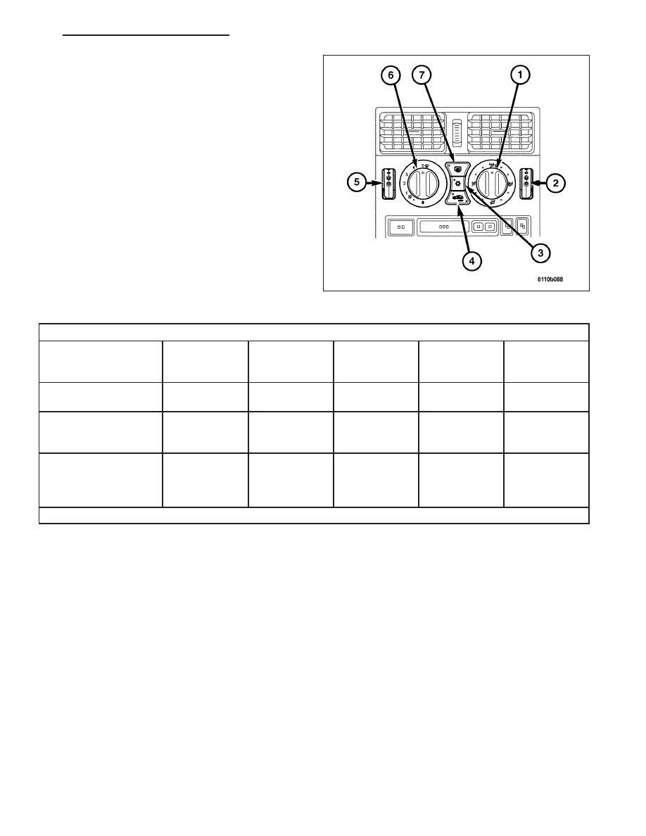
2. Set the A/C Heater mode control switch knob (2) in

the Panel position, the temperature control knob (7)
in the full cool position, the A/C button in the On
position, and the blower motor switch knob (6) in
the highest speed position.

3. Start the engine and hold the idle at 1,300 rpm with

the compressor clutch engaged.

4. The engine should be at operating temperature.

The doors and windows must be open.

5. Insert a thermometer in the driver side center A/C

(panel) outlet. Operate the engine for five minutes.

6. The compressor clutch may cycle, depending upon

the ambient temperature and humidity.

7. With the compressor clutch engaged, record the

discharge air temperature and the compressor dis-
charge pressure.

8. Compare the discharge air temperature to the Performance Temperature and Pressure chart.

Performance Temperature and Pressure

Ambient Air

Temperature and

Humidity

21° C

(70° F @ 80%

humidity)

27° C

(80° F @ 80%

humidity)

32° C

(90° F @ 80%

humidity)

38° C

(100° F @

50% humidity)

43° C

(110° F @ 20%

humidity)

Air Temperature at

Center Panel Outlet

10 to 13° C

(50 to 55° F)

14 to 17° C

(58 to 63° F)

15 to 18° C

(60 to 65° F)

17 to 20° C

(63 to 68° F)

14 to 17° C

(58 to 63° F)

Evaporator Inlet

Pressure at Charge

Port

241 to 276 kPa

(35 to 40 psi)

262 to 290

kPa

(38 to 42 psi)

269 to 296

kPa

(39 to 43 psi)

275 to 303

kPa

(40 to 44 psi)

262 to 290 kPa

(38 to 42 psi)

Compressor Discharge

Pressure

1241 to 1792

kPa

(180 to 260

psi)

1380 to 1930

kPa

(200 to 280

psi)

1380 to 1930

kPa

(200 to 280

psi)

1655 to 2206

kPa

(240 to 320

psi)

1567 to 2068

kPa

(220 to 300 psi)

Note: The discharge air temperatures will be lower if the humidity is less than the percentages shown.

ZH

HEATING & AIR CONDITIONING - SERVICE INFORMATION

24 - 71

9. Compare the compressor discharge pressure to the Performance Temperature and Pressure chart. If the com-

pressor discharge pressure is high, see the Pressure Diagnosis chart.

Pressure Diagnosis

Rapid compressor clutch cycling
(ten or more cycles per minute).

1. Low refrigerant system charge.

1. Test the A/C system for leaks.
Repair, evacuate and charge the
refrigerant system, if required.

Equal pressures, but the
compressor clutch does not engage.

1. No refrigerant in the refrigerant
system.

1. Test the A/C system for leaks.
Repair, evacuate and charge the
A/C, if required.

2. Faulty A/C compressor clutch
coil.

2. Test the compressor clutch coil
and replace, if required.

3. Faulty A/C pressure transducer.

3. Test the A/C high pressure
transducer and replace, if required.

4. Faulty A/C Heater Control
Module.

4. Test the A/C Heater Control
Module and replace, if required.

Normal pressures, but A/C
Performance Test air temperatures
at center panel outlet are too high.

1. Excessive refrigerant oil in
system.

1. Recover the refrigerant from the
refrigerant system and inspect the
refrigerant oil content. Restore the
refrigerant oil to the proper level, if
required.

2. Blend door inoperative or sealing
improperly.

2. Inspect the blend door for proper
operation and sealing and correct, if
required.

3. Blend door actuator faulty or
inoperative.

3. Replace if faulty.

The low side pressure is normal or
slightly low, and the high side
pressure is too low.

1. Low refrigerant system charge.

1. Test the refrigerant system for
leaks. Repair, evacuate and charge
the refrigerant system, if required.

2. Refrigerant flow through the
receiver/dryer is restricted.

2. Replace the restricted receiver/
drier, if required.

3. Refrigerant flow through the
evaporator is restricted.

Replace the restricted evaporator
coil, if required.

4. Faulty compressor.

Replace the compressor, if required.

The low side pressure is normal or
slightly high, and the high side
pressure is too high.

1. Condenser air flow restricted.

1. Check the condenser for
damaged fins, foreign objects
obstructing air flow through the
condenser fins, and missing or
improperly installed air seals. Clean,
repair, or replace components as
required.

2. Inoperative cooling fan.

2. Test the cooling fan and replace,
if required.

3. Refrigerant system overcharged.

3. Recover the refrigerant from the
refrigerant system. Charge the
refrigerant system to the proper
level, if required.

4. Air in the refrigerant system.

4. Test the refrigerant system for
leaks. Repair, evacuate and charge
the refrigerant system, if required.

24 - 72

HEATING & AIR CONDITIONING - SERVICE INFORMATION

ZH

Pressure Diagnosis

5. Engine overheating.

5. Test the cooling system and
repair, if required.

The low side pressure is too high,
and the high side pressure is too
low.

1. Accessory drive belt slipping.

1. Inspect the accessory drive belt
condition and tension. Tighten or
replace the accessory drive belt, if
required.

2. Faulty compressor.

2. Replace the compressor, if
required.

The low side pressure is too low,
and the high side pressure is too
high.

1. Restricted refrigerant flow
through the refrigerant lines.

1. Inspect the refrigerant lines for
kinks, tight bends or improper
routing. Correct the routing or
replace the refrigerant line, if
required.

2. Restricted refrigerant flow
through the A/C Expansion Valve.

2. Replace the Expansion Valve if
restricted.

3. Restricted refrigerant flow
through the condenser.

3. Replace the restricted condenser,
if required.

DIAGNOSIS AND TESTING - HEATER PERFORMANCE

Before performing the following tests, refer to Cooling for the procedures to check the radiator coolant level, ser-
pentine drive belt tension, radiator air flow and the radiator fan operation. Also be certain that the accessory vacuum
supply line is connected at the engine intake manifold for the manual temperature control system.

ZH

HEATING & AIR CONDITIONING - SERVICE INFORMATION

24 - 73

MAXIMUM HEATER OUTPUT

Engine coolant is delivered to the Heater Core through
two heater hoses. With the engine idling at normal
operating temperature, set the temperature control
knob (2 and 5) in the full hot position, the Mode Con-
trol Switch Knob (1) in the floor heat position, and the
Blower Motor Switch Knob (6) in the highest speed
position. Using a test thermometer, check the temper-
ature of the air being discharged at the HVAC housing
floor outlets. Compare the test thermometer reading to
the Temperature Reference chart.

Temperature Reference

Ambient Air Temperature

15.5° C

(60° F)

21.1° C

(70° F)

26.6° C

(80° F)

32.2° C

(90° F)

Minimum Air Temperature at
Floor Outlet

62.2° C

(144° F)

63.8° C

(147° F)

65.5° C

(150° F)

67.2° C

(153° F)

If the floor outlet air temperature is too low, refer to Cooling to check the engine coolant temperature specifications.
Both of the heater hoses should be hot to the touch. The coolant return heater hose should be slightly cooler than
the coolant supply heater hose. If the return hose is much cooler than the supply hose, locate and repair the engine
coolant flow obstruction in the cooling system. Refer to the Cooling section for the procedures.

OBSTRUCTED COOLANT FLOW

Possible locations or causes of obstructed coolant flow:

Pinched or kinked heater hoses.

Improper heater hose routing.

Plugged heater hoses or supply and return ports at the cooling system connections.

A plugged heater core.

If proper coolant flow through the cooling system is verified, and heater outlet air temperature is still low, a mechan-
ical problem may exist.

MECHANICAL PROBLEMS

Possible locations or causes of insufficient heat:

An obstructed cowl air intake.

Obstructed heater system outlets.

A blend door not functioning properly.

An air-bound system.

TEMPERATURE CONTROL

If the heater outlet air temperature cannot be adjusted with the temperature control knob(s) on the A/C Heater con-
trol panel, the following could require service:

The A/C heater control.

The blend door actuator(s).

The wire harness circuits for the A/C heater control or the blend door actuator(s).

24 - 74

HEATING & AIR CONDITIONING - SERVICE INFORMATION

ZH


Content   ..  990  991  992  993   ..