Chrysler Crossfire. Manual - part 917
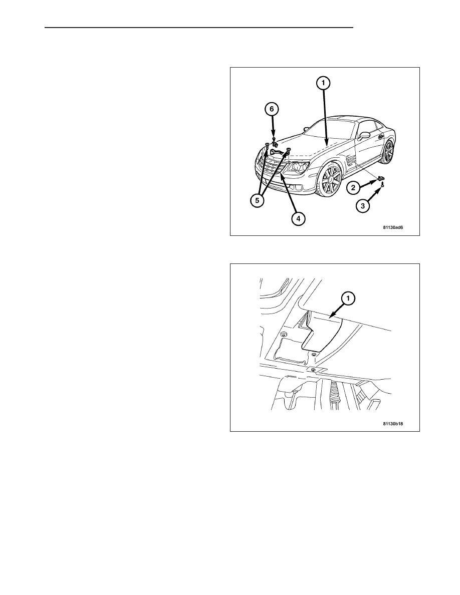
INSTALLATION
Note: Pay particular attention to the routing of the
hood latch release cable.
1. Install the hood latch release cable (1) between the
headlamp and the upper frame cross member.
2. Install the hood latch (6).
3. Install the cover.
4. Install the clip on the frame cross member.
5. Install the upper frame cross member.
6. Install the wire to the grommet (3) on the hood
latch release cable (2).
Note: Insure that hood latch release cable grom-
met is properly seated in the bulkhead.
7. Push the cable grommet into the bulkhead below
the fuse box.
8. Install the handle (1) to the arresting mechanism in
the cover and hook the hood latch release cable to
the handle.
9. Install the screw on handle (1).
10. Close the hood and check for proper operation.
ZH
HOOD
23 - 339