Chrysler Crossfire. Manual - part 796


  Index      Chrysler     Chrysler Crossfire - service repair manual 2005 year


Search            


Content   ..  794  795  796  797   ..


Chrysler Crossfire. Manual - part 796


PRESSURE ON A CONFINED FLUID

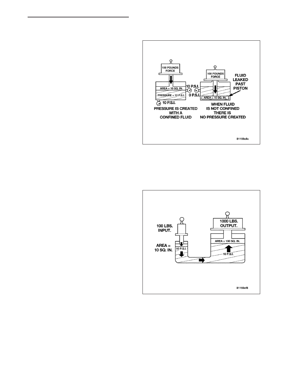
Pressure is exerted on a confined fluid by applying a
force to some given area in contact with the fluid. A
good example of this is a cylinder filled with fluid and
equipped with a piston that is closely fitted to the cyl-
inder wall. If a force is applied to the piston, pressure
will be developed in the fluid. Of course, no pressure
will be created if the fluid is not confined. It will simply
“leak” past the piston. There must be a resistance to
flow in order to create pressure. Piston sealing is
extremely important in hydraulic operation. Several
kinds of seals are used to accomplish this within a
transmission. These include but are not limited to
O-rings, D-rings, lip seals, sealing rings, or extremely
close tolerances between the piston and the cylinder
wall. The force exerted is downward (gravity), how-
ever, the principle remains the same no matter which
direction is taken. The pressure created in the fluid is
equal to the force applied, divided by the piston area.
If the force is 100 lbs., and the piston area is 10 sq.
in., then the pressure created equals 10 PSI. Another
interpretation of Pascal’s Law is that regardless of container shape or size, the pressure will be maintained through-
out, as long as the fluid is confined. In other words, the pressure in the fluid is the same everywhere within the
container.

FORCE MULTIPLICATION

Using the 10 PSI example used in the illustration, a
force of 1000 lbs. can be moved with a force of only
100 lbs. The secret of force multiplication in hydraulic
systems is the total fluid contact area employed. The
illustration shows an area that is ten times larger than
the original area. The pressure created with the
smaller 100 lb. input is 10 PSI. The concept “pressure
is the same everywhere” means that the pressure
underneath the larger piston is also 10 PSI. Pressure
is equal to the force applied divided by the contact
area. Therefore, by means of simple algebra, the out-
put force may be found. This concept is extremely
important, as it is also used in the design and opera-
tion of all shift valves and limiting valves in the valve
body, as well as the pistons, of the transmission,
which activate the clutches and bands. It is nothing
more than using a difference of area to create a dif-
ference in pressure to move an object.

ZH

AUTOMATIC - NAG1 SERVICE INFORMATION

21 - 333

PISTON TRAVEL

The

relationship

between

hydraulic

lever

and

a

mechanical lever is the same. With a mechanical
lever, it’s a weight-to-distance output rather than a
pressure-to-area output. Using the same forces and
areas as in the previous example, the smaller piston
has to move ten times the distance required to move
the larger piston one inch. Therefore, for every inch
the larger piston moves, the smaller piston moves ten
inches. This principle is true in other instances also. A
common garage floor jack is a good example. To raise
a car weighing 2000 lbs., an effort of only 100 lbs.
may be required. For every inch the car moves
upward, the input piston at the jack handle must move
20 inches downward.

PLANETARY GEARTRAIN

DESCRIPTION

Three planetary gear sets are used to produce the different gear ratios. These are located in the mechanical part of
the transmission as the front, middle and rear planetary gear sets.

OPERATION

The annulus gear (1) and sun gear (3) elements of a
planetary gear system are alternately driven and
braked by the actuating elements of the multi-plate
clutch and multiple-disc brake. The planetary pinion
gears (2) can turn on the internal gearing of the annu-
lus gear (1) and on the external gearing of the sun
gear (3). This allows for a variety of gear ratios and
the reversal of the rotation direction without the need
for moving gear wheels or shift collars. When two
components of the planetary gear set are locked
together, the planetary gear set is locked and turns as
a closed unit.

The torque and engine speed are converted according
to the lever ratios and the ratio of the number of teeth
on the driven gears to that on the drive gears, and is
referred to as the gear ratio. The overall ratio of a
number of planetary gear sets connected in series is
obtained by multiplying the partial ratios.

21 - 334

AUTOMATIC - NAG1 SERVICE INFORMATION

ZH

DISASSEMBLY

1. Remove the upper two visible teflon rings (1) from the output shaft with center planetary carrier (2).

2. Remove the retaining ring (11), shim (10), axial needle bearing (9) and thrust washer (8) from the output shaft

with center planetary carrier (2).

3. Remove the driving clutch K3 (7).

4. Remove the rear hollow shaft/freewheel F2 (6) from the output shaft with center planetary carrier (2).

5. Remove the rear planetary gear set (5) with integrated tubular shaft of center gear set from the output shaft with

center planetary carrier (2).

6. Remove the thrust washer (4).

ZH

AUTOMATIC - NAG1 SERVICE INFORMATION

21 - 335

ASSEMBLY

1. Mount the thrust washer (4) with the collar pointing towards the planet carrier.

2. Mount the rear planetary gear set (5) with the integrated tubular shaft of the center gear set on the output shaft

with center planetary carrier (2).

3. Using grease, install the lower three teflon rings (1) in the groove so that the joint stays together.

4. Put the rear hollow shaft/freewheel F2 (6) onto the output shaft.

5. Install the clutch K3 (7).

6. Mount the retaining ring (11), shim, axial needle bearing (9) and thrust washer (8).

7. Using grease, insert the upper two teflon rings (1) in the groove so that the joint remains together.

8. Inspect for axial play between shim (10) and retaining ring (11). Check axial play “S” between shim (10) and

retaining ring (1) using a feeler gauge. Clearance should be 0.15-0.6 mm (0.006-0.024 in.). Shims are available
in thicknesses of 3.0 mm (0.118 in.), 3.4 mm (0.134 in.), and 3.7 mm (0.146 in.). Adjust as necessary.

Note: During the test, apply a contact force by hand to K3 in the direction of the output shaft.

SHIFT INTERLOCK SOLENOID

DESCRIPTION

The typical electrical solenoid used in automotive applications is a linear actuator. It is a device that produces
motion in a straight line. This straight line motion can be either forward or backward in direction, and short or long
distance.

A solenoid is an electromechanical device that uses a magnetic force to perform work. It consists of a coil of wire,
wrapped around a magnetic core made from steel or iron, and a spring loaded, movable plunger, which performs
the work, or straight line motion.

21 - 336

AUTOMATIC - NAG1 SERVICE INFORMATION

ZH


Content   ..  794  795  796  797   ..