Chrysler Crossfire. Manual - part 666


  Index      Chrysler     Chrysler Crossfire - service repair manual 2005 year


Search            


Content   ..  664  665  666  667   ..


Chrysler Crossfire. Manual - part 666


INTAKE MANIFOLD

DESCRIPTION

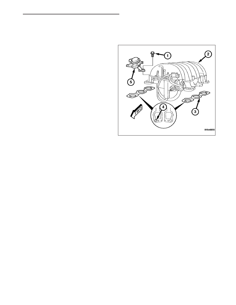
A magnesium two-stage resonance intake manifold (1)
has long runners to enhance low-speed torque and
shorter runners for added horsepower. The runners,
and the plenum chamber that feeds them, nest
between the cylinder banks. Complex components of
the multi-piece die-cast manifold are adhesive bonded
together.

OPERATION

A variable intake manifold provides a marked supercharging effect to air flow entering the cylinders as the intake
valve closes. Long individual tubes for each cylinder that enhance low-speed torque have a tuned length of 32.9
inches (835 mm). This length is achieved by coiling the tubes in the valley of the cylinder block. In these tubes, the
air rotates 450 degrees from entry to cylinder head. To achieve a similar effect at higher speeds, a tube length of
18.3 inches (465 mm) is used. Butterfly valves in the walls of the long tubes, operated by the engine control com-
puter, switch the flow between long and short flow paths at approximately 3700 rpm. The engine speed for switcho-
ver to the short tubes provides an imperceptible change in engine torque, because the maximum supercharging
effect is consistent throughout the 2000 to 5000-rpm speed range.

DIAGNOSIS AND TESTING - INTAKE MANIFOLD LEAKS

An intake manifold air leak is characterized by lower than normal manifold vacuum. Also, one or more cylinders may
not be functioning.

WARNING: USE EXTREME CAUTION WHEN THE ENGINE IS OPERATING. DO NOT STAND IN A DIRECT LINE
WITH THE FAN. DO NOT PUT YOUR HANDS NEAR THE PULLEYS, BELTS OR THE FAN. DO NOT WEAR
LOOSE CLOTHING.

1. Start the engine.

2. Spray a small stream of water (Spray Bottle) at the suspected leak area.

3. If engine RPM’S change, the area of the suspected leak has been found.

4. Repair as required.

REMOVAL

1. Disconnect the negative battery cable.

2. Remove the air cleaner housing. (Refer to 9 - ENGINE/AIR INTAKE SYSTEM/AIR CLEANER HOUSING -

REMOVAL).

3. Remove the mass air flow sensor. (Refer to 14 - FUEL SYSTEM/FUEL INJECTION/MANIFOLD AIR FLOW

(MAF) SENSOR - REMOVAL).

ZH

ENGINE - 3.2L SERVICE INFORMATION

9 - 809

4. Remove the fuel rail with fuel injectors. (Refer to 14 - FUEL SYSTEM/FUEL INJECTION/FUEL INJECTOR -

REMOVAL).

5. Disconnect the vacuum lines to the EGR valve, brake booster, crankcase ventilator and purge valve from the

intake manifold.

6. Disconnect the engine harness connectors.

7. Disconnect the EGR pipe (1) at the EGR valve (2).

8. Remove the air pump switchover valves (4).

9. Remove the bolts, the intake manifold (1) and the

gaskets (2).

INSTALLATION

1. Clean the gasket surfaces of the cylinder heads and the intake manifold.

9 - 810

ENGINE - 3.2L SERVICE INFORMATION

ZH

2. Position the intake manifold (1) on the cylinder

heads with new gaskets (2) in place.

3. Install the intake manifold bolts and tighten to 20

N·m (15 ft. lbs.).

4. Install the air pump switchover valves (4). Tighten

the bolts to 20 N·m (15 ft. lbs.).

5. Connect the EGR pipe fitting (1) to the EGR valve

(2). Tighten the EGR pipe fitting to 40 N·m (30 ft.
lbs.).

6. Install the mass air flow sensor. (Refer to 14 -

FUEL SYSTEM/FUEL INJECTION/MANIFOLD AIR
FLOW (MAF) SENSOR - INSTALLATION).

7. Connect the engine harness connectors.

8. Connect the vacuum lines at the crankcase ventila-

tor, purge valve, EGR valve, and the brake booster.

9. Install the fuel rail with fuel injectors. (Refer to 14 -

FUEL SYSTEM/FUEL INJECTION/FUEL INJEC-
TOR - INSTALLATION).

10. Install the air cleaner housing. (Refer to 9 -

ENGINE/AIR INTAKE SYSTEM/AIR CLEANER
HOUSING - REMOVAL).

11. Connect the negative battery cable.

12. Start the engine and check for leaks.

EXHAUST MANIFOLD

DESCRIPTION

Thin-wall air-gap construction for the exhaust manifolds reduces underhood temperature by keeping heat in the
exhaust stream. This also allows the catalytic converter to be mounted in a more advantageous position for pack-
aging, under the floor instead of close to the engine. Stainless steel inner manifolds, separated by an air space from
two-piece stainless steel outer shells, reduce heat loss to the air in much the same way thermo-pane glass reduces
heat loss through windows. Hydro-formed inner manifolds, through which the exhaust flows, provide precise dimen-
sional control. They are assembled to the cylinder head flanges, exhaust pipe flanges and the outer shells by laser
welding.

ZH

ENGINE - 3.2L SERVICE INFORMATION

9 - 811

REMOVAL

LEFT SIDE

1. Disconnect the negative battery cable.

2. Remove the air cleaner housing. (Refer to 9 - ENGINE/AIR INTAKE SYSTEM/AIR CLEANER HOUSING -

REMOVAL).

3. Raise and support the vehicle.

4. Remove the lower splash shield screws (1) and the

splash shield.

5. Remove the left side catalytic converter. (Refer to 11 - EXHAUST SYSTEM/CATALYTIC CONVERTER -

INSTALLATION).

6. Remove the exhaust manifold nuts (3).

7. Lower the vehicle.

8. Remove the left side exhaust manifold (1) and gas-

kets (2) from the engine compartment.

9 - 812

ENGINE - 3.2L SERVICE INFORMATION

ZH


Content   ..  664  665  666  667   ..