Chrysler Crossfire. Manual - part 478
(P0113) INTAKE AIR TEMPERATURE SENSOR CIRCUIT HIGH (EXCEPT SRT) (CONTINUED)
2.
CHECK FOR CURRENT DTC
Note: If the PCM detects and stores a DTC, the PCM also stores
the engine/vehicle operating conditions under which the DTC was
set. Some of these conditions are displayed on the DRB III
T
at the
same time the DTC is displayed.
Note: Before erasing stored DTCs, record these conditions.
Attempting to duplicate these conditions may assist when check-
ing for an active DTC.
Turn the ignition on.
With the DRB III
T
, erase PCM DTCs.
Note: It maybe necessary to road test the vehicle for this DTC to
set.
With the DRB III
T
, read PCM DTCs.
Did this DTC set again?
Yes
>> Go To 3
No
>> Go To 10
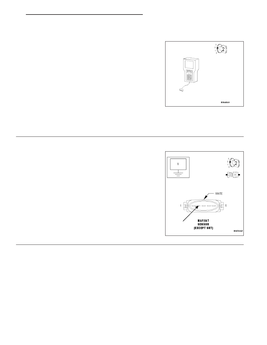
3.
MEASURE THE VOLTAGE OF THE ENGINE CONTROL RELAY OUPUT CIRCUIT
Turn the ignition off.
Disconnect the MAF/IAT Sensor harness connector.
Note: Check connectors — Clean/repair as necessary.
Turn the ignition on.
Measure the voltage of the Fused Engine Control Relay Output circuit
at the MAF/IAT Sensor harness connector.
Is the voltage above 10 volts?
Yes
>> Go To 4
No
>> Repair the Fused Engine Control Relay Ouput circuit for
an open.
Perform POWERTRAIN VERIFICATION TEST - VER 2.
ZH
ENGINE - ELECTRICAL DIAGNOSTICS
9 - 57