Chrysler Crossfire. Manual - part 466
(P0101) MAF SENSOR PERFORMANCE (CONTINUED)
When Monitored and Set Condition
•
When Monitored: With the engine running and no fault in the throttle valve actuator.
•
Set Condition: The Mass Air Flow (MAF) Sensor value is less than 16 kg/h when the throttle valve angle is
greater than 14° for approximately 5 seconds, or the MAF Sensor reading is greater than a calculated value
that is determined by engine speed and throttle valve angle for approximately 5 seconds.
POSSIBLE CAUSES
FUSED ENGINE CONTROL RELAY OUTPUT CIRCUIT OPEN
FUSED ENGINE CONTROL RELAY OUTPUT CIRCUIT SHORT TO GROUND
SENSOR GROUND CIRCUIT OPEN
MASS AIR FLOW SENSOR SIGNAL CIRCUIT OPEN
MASS AIR FLOW SENSOR SIGNAL CIRCUIT SHORT TO GROUND
5-VOLT SUPPLY CIRCUIT OPEN
5-VOLT SUPPLY CIRCUIT SHORT TO GROUND
MASS AIR FLOW SENSOR
POWERTRAIN CONTROL MODULE
For a complete Powertrain Control Module Circuit Diagram, (Refer to 9 - ENGINE - SCHEMATICS AND DIA-
GRAMS).
Diagnostic Test
1.
CHECK FOR CURRENT DTC
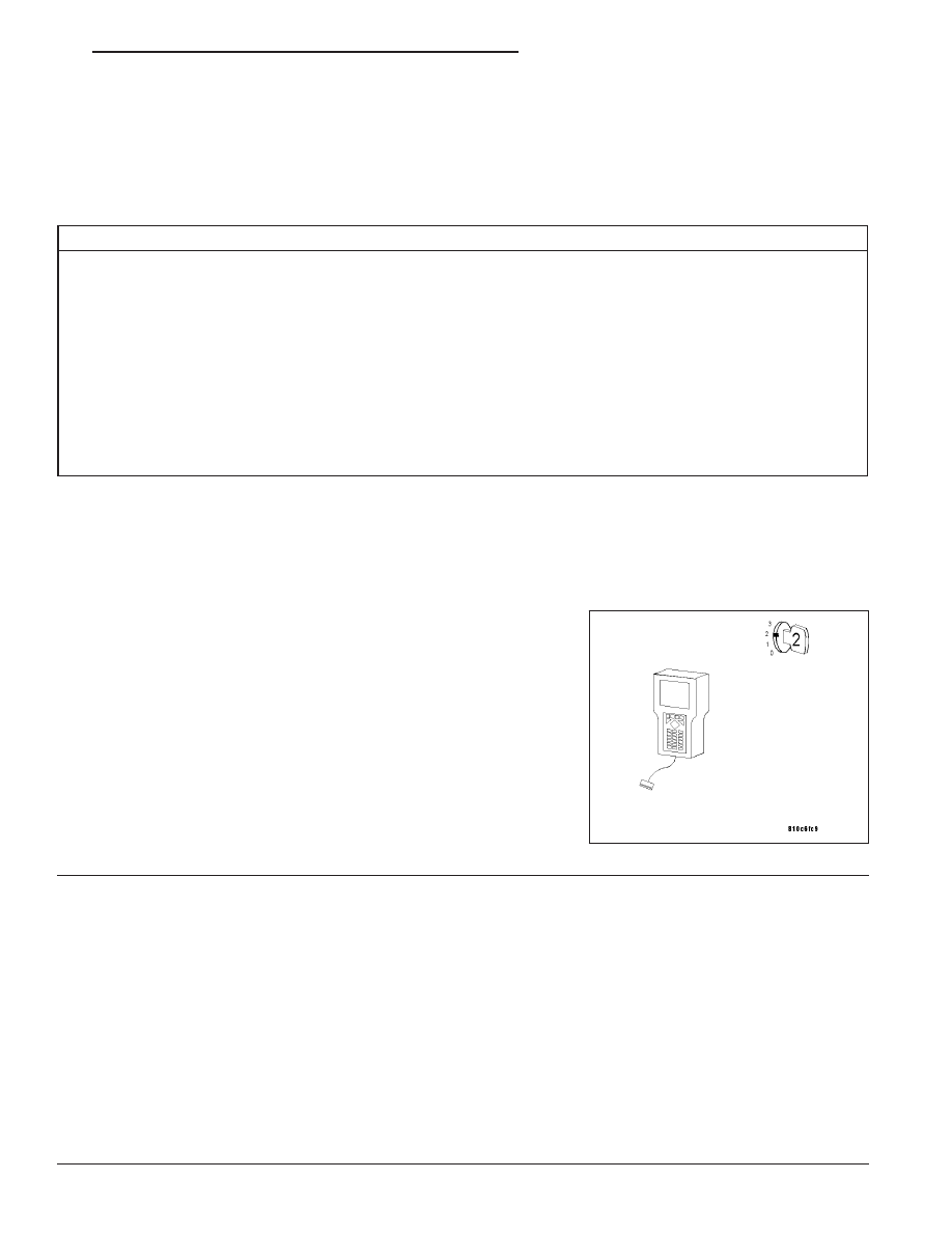
Turn the ignition on.
With the DRB III
T
, read PCM DTCs.
Is this DTC present?
Yes
>> For complete diagnosis of this DTC, refer to (P0102)
MASS AIR FLOW CIRCUIT.
No
>> Go To 2
2.
INTERMITTENT WIRING AND CONNECTORS
The conditions necessary to set this DTC are not present at this time.
Note: Check connectors — Clean/repair as necessary. Poor pin to terminal connections can set DTCs. Using
the wiring diagram/schematic as a guide, inspect the wiring and connectors specific to this DTC. Wiggle the
wires while checking for shorts and open circuits.
Note: Check for any Technical Service Bulletins that may apply.
Were there any problems found?
Yes
>> Repair as necessary.
Perform POWERTRAIN VERIFICATION TEST - VER 2.
No
>> The condition that caused this DTC to set is currently not present. Inspect the related wiring harness for
a possible intermittent condition.
ZH
ENGINE - ELECTRICAL DIAGNOSTICS
9 - 9