Chrysler Crossfire. Manual - part 367
SENTRY KEY ANTENNA CIRCUIT (CONTINUED)
When Monitored and Set Condition
•
When Monitored: Ignition on.
•
Set Condition: The Sentry Key Remote Entry Module (SKREEM) detects a Sentry Key Antenna circuit mal-
function.
POSSIBLE CAUSES
SENTRY KEY ANTENNA RING
SENTRY KEY REMOTE ENTRY MODULE
For a complete Sentry Key Remote Entry (SKREEM) Circuit Diagram, (Refer to 8 - ELECTRICAL/VEHICLE THEFT
SECURITY - SCHEMATICS AND DIAGRAMS).
Diagnostic Test
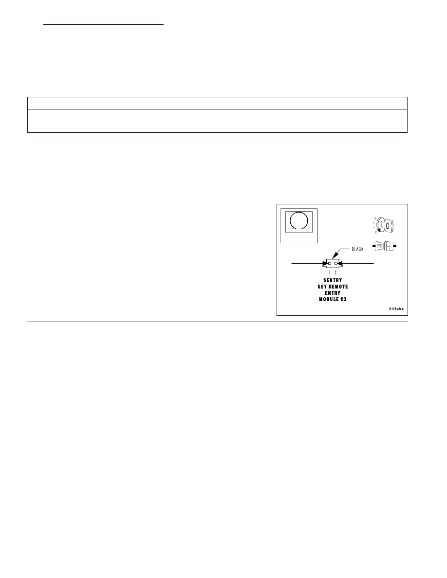
1.
MEASURE THE RESISTANCE OF THE SENTRY KEY ANTENNA CIRCUIT
Disconnect
the
Sentry
Key Antenna
Ring
connector
from
the
SKREEM.
Turn the ignition on.
Measure the resistance of the Sentry Key Antenna circuit from cavity 1
to cavity 2 of the connector.
Is the resistance between 4 and 6 ohms?
Yes
>> Replace the Sentry Key Remote Entry Module.
Perform SENTRY KEY VERIFICATION TEST.
No
>> Replace the Sentry Key Antenna Ring assembly.
Perform SENTRY KEY VERIFICATION TEST.
ZH
VEHICLE THEFT SECURITY - ELECTRICAL DIAGNOSTICS
8Q - 41