Chrysler Crossfire. Manual - part 356


  Index      Chrysler     Chrysler Crossfire - service repair manual 2005 year


Search            


Content   ..  354  355  356  357   ..


Chrysler Crossfire. Manual - part 356


SPEED CONTROL - SERVICE INFORMATION

TABLE OF CONTENTS

page

page

SPEED CONTROL - SERVICE INFORMATION

DESCRIPTION

. . . . . . . . . . . . . . . . . . . . . . . . . . 9

OPERATION

. . . . . . . . . . . . . . . . . . . . . . . . . . . . 9

SWITCH

REMOVAL

. . . . . . . . . . . . . . . . . . . . . . . . . . . . . 10

INSTALLATION

. . . . . . . . . . . . . . . . . . . . . . . . . 11

SPEED CONTROL - SERVICE INFORMATION

DESCRIPTION

WARNING: THE USE OF SPEED CONTROL IS NOT RECOMMENDED WHEN DRIVING CONDITIONS DO NOT
PERMIT MAINTAINING A CONSTANT SPEED, SUCH AS IN HEAVY TRAFFIC OR ON ROADS THAT ARE WIND-
ING, ICY, SNOW COVERED, OR SLIPPERY.

Note: A cable and a vacuum controlled servo are not used. This is a servo-less system.

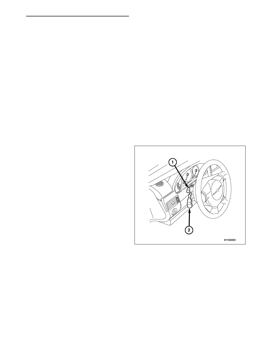
The Speed Control System is fully electronically con-
trolled by the Powertrain Control Module (PCM). Con-
trol of the Speed Control System is accomplished by a
Speed Control Switch (1) which is located just above
the Multifunction Switch (2). The Speed Control Sys-
tem also uses other components of the vehicle to
accomplish its tasks. The five other major components
used are as follows; The PCM, Accelerator Pedal
Position Sensor, Kickdown Switch (Automatic Trans-
mission), Throttle Body and the Clutch Pedal Position
Switch (Manual Transmission). The Speed Control
System is designed to operate at speeds above 25
MPH (40 km/h).

OPERATION

When speed control operation is requested by the Speed Control Switch. The Powertrain Control Module allows a
set speed to be stored in its memory for speed control. To store a set speed, press either of the SET switch func-
tions while the vehicle is moving, at a speed above 25 MPH (40 km/h). In order for the speed control to engage, the
brakes cannot be applied, nor can the gear selector be indicating the transmission is in Park or Neutral.

The speed control can be disengaged manually by:

Applying the brake pedal

Pressing the speed control switch to OFF

Depressing the clutch pedal (if equipped).

Note: Turning the Speed Control Switch OFF or turning OFF the ignition switch will erase the set speed
stored in the PCM.

For added safety, the Speed Control System is programmed to disengage for any of the following conditions:

An indication of Park or Neutral

ZH

SPEED CONTROL - SERVICE INFORMATION

8P - 9

A rapid increase in RPM (indicates that the clutch has been disengaged)

Excessive engine RPM (indicates that the transmission may be in a low gear)

The speed signal increases at a rate of 10 MPH per second (indicates that the coefficient of friction between
the road surface and tires is extremely low)

The speed signal decreases at a rate of 10 MPH per second (indicates that the vehicle may have decelerated
at an extremely high rate)

Once the speed control has been disengaged, pulling
the Speed Control Switch forward into the RESUME
position (when speed is greater than 30 MPH)
restores the vehicle to the target speed that was
stored in the PCM.

While the speed control is engaged, the driver can
increase the vehicle speed by pushing the Speed
Control Switch upward into the ACCEL,SET position.
The new target speed is stored in the PCM when the
ACCEL,SET switch position is released. The PCM
also has a “tap-up” feature in which vehicle speed
increases at a rate of approximately 2 MPH for each
momentary switch activation of the ACCEL,SET switch
position.

A “tap down” feature is used to decelerate without dis-
engaging the Speed Control System. To decelerate
from an existing recorded target speed, momentarily
push the speed control switch downward into the
DECEL,SET switch position. For each switch activa-
tion, speed will be lowered approximately 1 MPH

SWITCH

REMOVAL

WARNING: REFER TO RESTRAINTS BEFORE ATTEMPTING ANY DOOR, SEAT, STEERING WHEEL, STEER-
ING COLUMN, OR INSTRUMENT PANEL COMPONENT DIAGNOSIS OR SERVICE. FAILURE TO TAKE THE
PROPER PRECAUTIONS COULD RESULT IN ACCIDENTAL AIRBAG DEPLOYMENT AND POSSIBLE PER-
SONAL INJURY.(Refer to 8 - ELECTRICAL/RESTRAINTS - WARNING).

1. Disconnect the negative battery cable.

2. Remove the steering wheel. (Refer to 19 - STEER-

ING/COLUMN/STEERING WHEEL - REMOVAL).

3. Remove the clockspring. (Refer to 8 - ELECTRI-

CAL/RESTRAINTS/CLOCKSPRING - REMOVAL).

4. Remove the lower instrument panel. (Refer to 23 -

BODY/INSTRUMENT

PANEL/INSTRUMENT

PANEL ASSEMBLY - REMOVAL).

5. Remove the screw (1) attaching the speed control

switch to the multifunction switch.

6. Disconnect the electrical connectors on the steer-

ing column.

7. Disconnect the wiring from the column.

8P - 10

SPEED CONTROL - SERVICE INFORMATION

ZH

INSTALLATION

1. Connect the wiring to the column.

2. Connect the electrical connectors on the steering

column.

3. Install the screw (1) attaching the speed control

switch to the multifunction switch.

4. Install the lower instrument panel. (Refer to 23 -

BODY/INSTRUMENT

PANEL/INSTRUMENT

PANEL ASSEMBLY - INSTALLATION).

5. Install the clockspring. (Refer to 8 - ELECTRICAL/

RESTRAINTS/CLOCKSPRING - INSTALLATION).

6. Install the steering wheel. (Refer to 19 - STEER-

ING/COLUMN/STEERING WHEEL - INSTALLA-
TION).

7. Connect the negative battery cable.

ZH

SPEED CONTROL - SERVICE INFORMATION

8P - 11


Content   ..  354  355  356  357   ..