Chrysler Crossfire. Manual - part 346
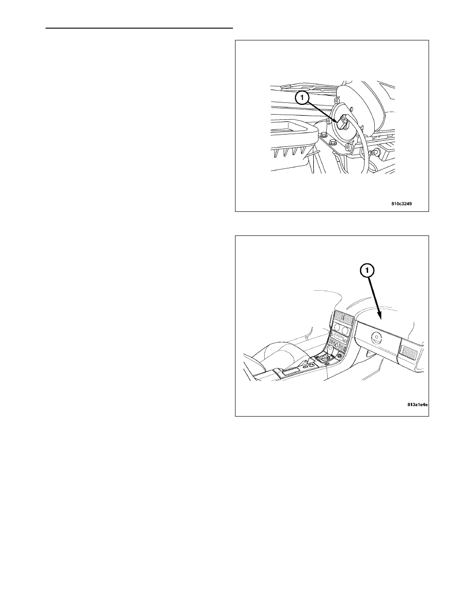
4. Connect the passenger airbag squib harness con-
nector (1).
CAUTION: Use caution when connecting the squib
harness connector to the passenger airbag inflator
connector receptacle. Improper assembly of these
pigtail wires and their connector insulators can
result in damage to the airbag circuits or connec-
tor insulators.
5. Install the top section of the instrument panel
(1)(Refer to 23 - BODY/INSTRUMENT PANEL/IN-
STRUMENT PANEL ASSEMBLY - INSTALLATION).
6. Do not reconnect the negative battery cable at this
time. Perform the Supplemental Restraint System
verification test procedure after servicing any Sup-
plemental Restraint System component. (Refer to 8
-
ELECTRICAL/RESTRAINTS
-
STANDARD
PROCEDURE).
ON / OFF SWITCH INDICATOR MODULE
DESCRIPTION
The passenger seat occupant simulator is located on the front side of the passenger floor access panel. The mod-
ule is attached to the access panel with a plastic wire tie. The multiplexed DC voltage signal received from the
passenger airbag switch is converted into a digital signal andsent to the occupant restraint controller.
OPERATION
The passenger seat occupant simulator receives a multiplexed DC voltage signal from the passenger airbag on/off
switch. The signal is then converted into a digital signal and sent to the occupant restraint controller.
With the passenger airbag On/Off switch in the OFF position, the occupant restraint controller provides a ground for
the Passenger Air Bag Off indicator, and disables the passenger airbag.
With the passenger airbag On/Off switch in the ON position, the occupant restraint controller allows full operation of
the passenger airbag.
ZH
RESTRAINTS - SERVICE INFORMATION
8O - 107