Chrysler Crossfire. Manual - part 257
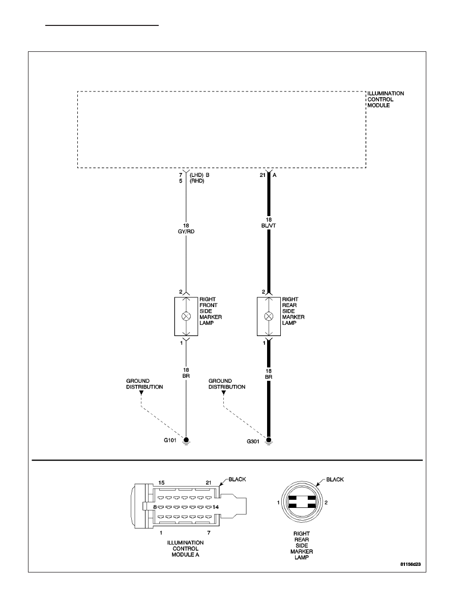
*RIGHT REAR SIDE MARKER LAMP INOPERATIVE
ZH
LAMPS/LIGHTING - EXTERIOR - ELECTRICAL DIAGNOSTICS
8L - 41
|
|
|
*RIGHT REAR SIDE MARKER LAMP INOPERATIVE ZH LAMPS/LIGHTING - EXTERIOR - ELECTRICAL DIAGNOSTICS 8L - 41 |