Chrysler Crossfire. Manual - part 213


  Index      Chrysler     Chrysler Crossfire - service repair manual 2005 year


Search            


Content   ..  211  212  213  214   ..


Chrysler Crossfire. Manual - part 213


REMOVAL

1. Disconnect the negative battery cable.

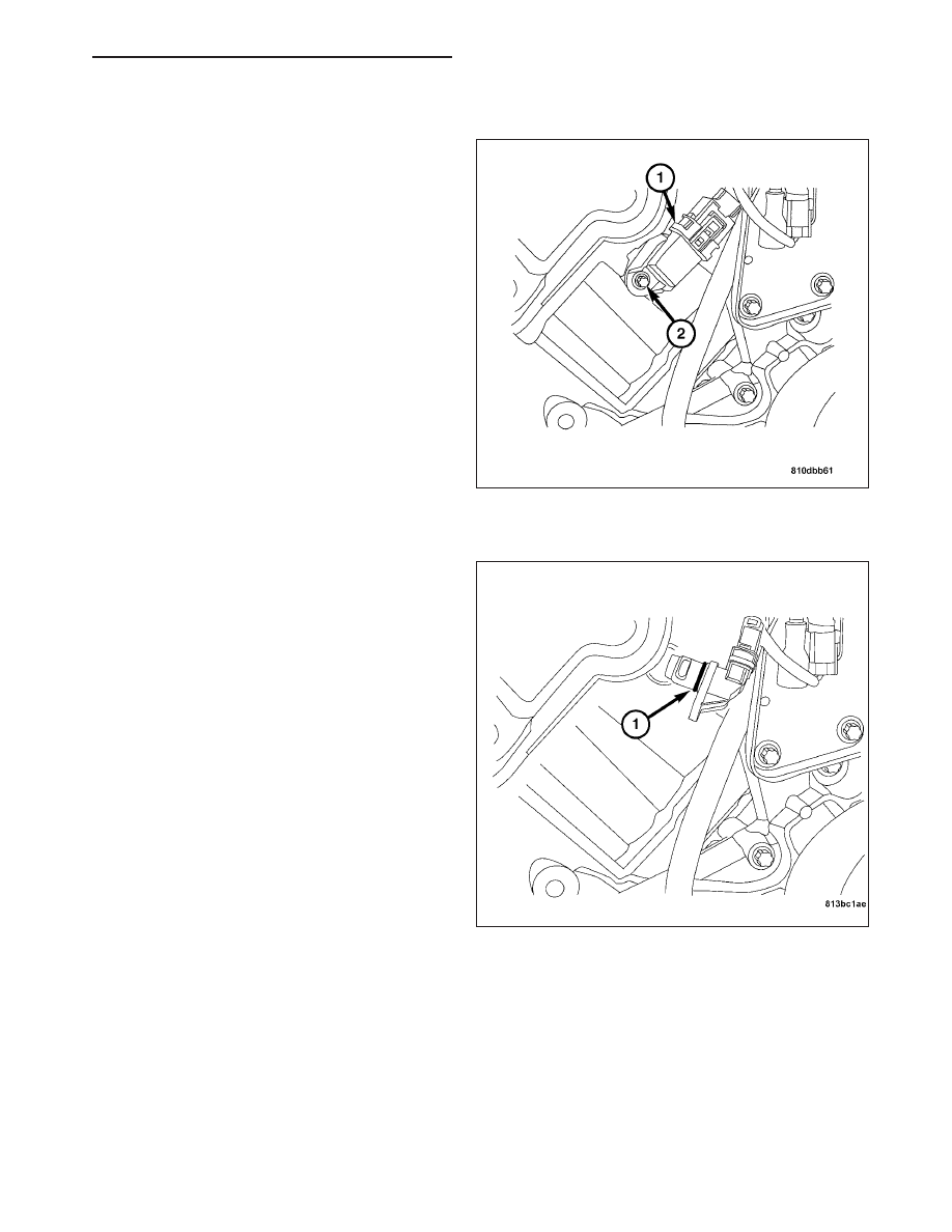
2. Disconnect the camshaft position sensor harness

connector (1).

3. Remove the retaining bolt (2).

4. Remove the camshaft position sensor from the cyl-

inder head.

INSTALLATION

Note: Lubricate the camshaft position sensor
O-ring with engine oil.

1. Inspect the camshaft position sensor O-ring (1) for

damage.

2. Lubricate the camshaft position sensor O-ring as

necessary.

ZH

IGNITION SYSTEM - SERVICE INFORMATION

8I - 7

3. Position the camshaft position sensor on the cylin-

der head.

4. Install the retaining bolt (2). Tighten the retaining

bolt to 8 N·m (71 in. lbs.).

5. Connect the camshaft position sensor harness con-

nector (1).

6. Connect the negative battery cable.

IGNITION COIL

DESCRIPTION

The Ignition Coils are mounted on the cylinder head covers. They are connected to the spark plugs via short spark
plug cables. The coils are a dual coil type construction. Utilizing two separate coils in one coil pack.

8I - 8

IGNITION SYSTEM - SERVICE INFORMATION

ZH

OPERATION

The Ignition Coils are powered by Fuse 11 in the
Underhood Accessory Fuse Block. The Powertrain
Control Module (PCM) controls the current flow
through the primary side of the coils by toggling the
control circuits. The secondary voltage is generated
when the primary current flow stops, and the magnetic
field created by the current flow in the primary wind-
ings collapses. The collapsing magnetic field induces
a voltage into the secondary windings and creates a
high voltage surge that is sent to the spark plug wire.

Each cylinder has a double coil set, and its own ded-
icated spark plug wire. The coils are controlled by the
PCM. The coils can be fired simultaneously or in
phases. The coils are phase-shift triggered, firing
plugs A-B, then B-A, then A-B etc. The offset between
the plug firing varies from 0° to 10°. Timing can be
retarded by as much as 14.5°.

ZH

IGNITION SYSTEM - SERVICE INFORMATION

8I - 9

REMOVAL

REMOVAL

1. Disconnect the negative battery cable (2).

2. Remove the air cleaner inlet tubes (2).

3. Remove the engine cover (1). Grasp both corners

of the engine cover, and pull up firmly.

8I - 10

IGNITION SYSTEM - SERVICE INFORMATION

ZH


Content   ..  211  212  213  214   ..