Chrysler Crossfire. Manual - part 178
4. Install the foam insulation panel.
Note: Make sure the aligning tabs of the base
plate are positioned correctly in the foam insulat-
ing panel.
5. Install the carpeting in the passenger footwell.
6. Install the floor mat to the carpet.
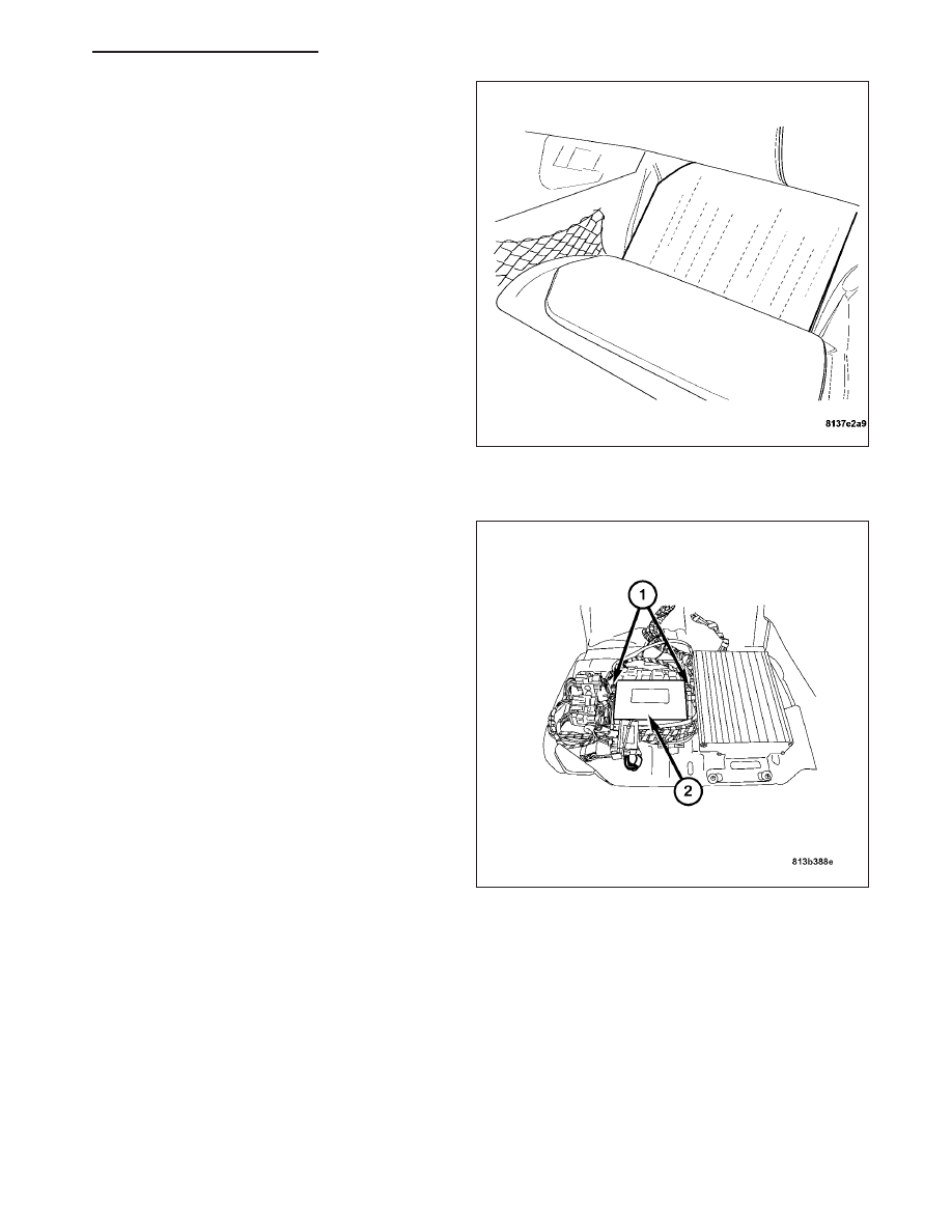
INSTALLATION
1. Connect the TCM harness connectors and attach
the TCM to the base plate with the two retaining
screws (1).
ZH
ELECTRONIC CONTROL MODULES - SERVICE INFORMATION
8E - 89