Chrysler Crossfire. Manual - part 169
*NO RESPONSE FROM TRANSMISSION CONTROL MODULE (CONTINUED)
5.
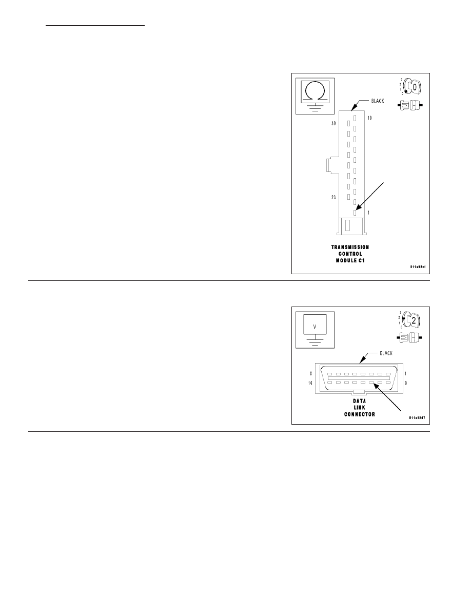
SCI TRANSMIT CIRCUIT SHORTED TO GROUND
With the ignition off.
Measure the resistance between ground and the SCI Transmit circuit.
Is the resistance above 100 kohms?
Yes
>> Go to 6
No
>> Repair the SCI Transmit circuit for a short to ground.
Perform NAG1 TRANSMISSION VERIFICATION TEST.
6.
SCI TRANSMIT CIRCUIT SHORTED TO VOLTAGE
Turn the ignition on.
Measure the voltage of the SCI Transmit circuit at the DLC.
Is the voltage below 0.5 volt?
Yes
>> Replace the Transmission Control Module. (Refer to 8 -
ELECTRICAL/ELECTRONIC
CONTROL
MODULES/
TRANSMISSION CONTROL MODULE - REMOVAL) .
Perform NAG1 TRANSMISSION VERIFICATION TEST.
No
>> Repair the SCI Transmit circuit for a short to voltage.
Perform NAG1 TRANSMISSION VERIFICATION TEST.
ZH
ELECTRONIC CONTROL MODULES - ELECTRICAL DIAGNOSTICS
8E - 53