Content .. 1018 1019 1020 1021 ..
Chrysler Crossfire. Manual - part 1020
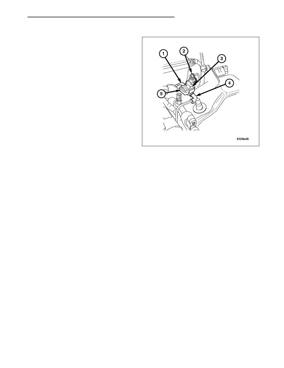
INSTALLATION
1. Install solenoid (3) on bracket (5).
2. Connect vapor hoses (1 and 4) to solenoid (3).
3. Connect connector (2) to solenoid (3).
FUEL FILLER CAP
DESCRIPTION
The plastic/metal Fuel Filler Cap is installed with a 1/4 turn onto the end of the fuel filler tube. Its purpose is to
retain vapors and fuel in the fuel tank.
OPERATION
The Fuel Filler Cap incorporates a two-way relief valve that is closed to atmosphere during normal operating con-
ditions. The relief valve is calibrated to open when a pressure of 172 mbar (2.5 psi) or vacuum of 20 mbar (8
inH2O) occurs in the fuel tank. When the pressure or vacuum is relieved, the valve returns to the normally closed
position.
WARNING: REMOVE THE FUEL FILLER CAP IN ORDER TO RELEASE FUEL TANK PRESSURE BEFORE DIS-
CONNECTING ANY FUEL SYSTEM COMPONENT.
ORVR
DESCRIPTION
The Onboard Refueling Vapor Recovery (ORVR) System is used to remove excess vapors in the fuel tank during
refueling.
ZH
EVAPORATIVE EMISSIONS
25 - 19