Index Chrysler Chrysler Crossfire - service repair manual 2005 year
Search
Content .. 63 64 65 66 ..
Chrysler Crossfire. Manual - part 65
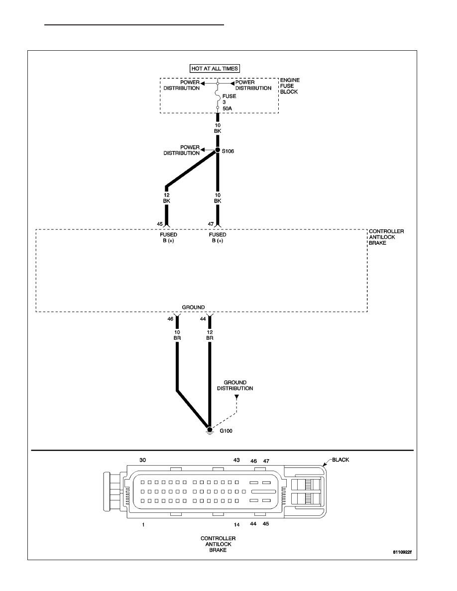
CAB SYSTEM OVERVOLTAGE
ZH
BRAKES - ABS ELECTRICAL DIAGNOSTICS
5 - 93