Chrysler Crossfire. Manual - part 54


  Index      Chrysler     Chrysler Crossfire - service repair manual 2005 year


Search            


Content   ..  52  53  54  55   ..


Chrysler Crossfire. Manual - part 54


REMOVAL - RHD

CAUTION: Do not get brake fluid on any painted surfaces. Brake fluid can damage paint.

1. Disconnect the negative battery cable.

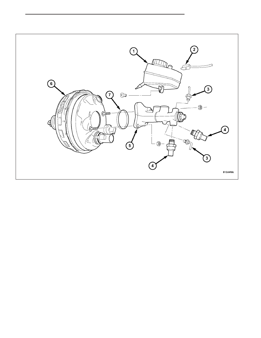
2. Disconnect the brake fluid level sensor harness connector (2) from the reservoir (1).

3. Disconnect the master cylinder brake fluid pressure sensor (4) harness connectors.

4. Remove brake lines (3) from master cylinder (5).

5. Remove the nuts that attach the master cylinder (5) to the booster studs.

WARNING: DO NOT TILT THE MASTER BRAKE CYLINDER WHEN REMOVING FROM THE BRAKE BOOSTER.
IF TILTED, THE BRAKE ROD CAN BE DISCONNECTED FROM THE MASTER CYLINDER.

6. Remove the master cylinder (5) from the booster (6).

ZH

BRAKES - BASE

5 - 49

INSTALLATION

INSTALLATION

1. Bleed the master cylinder on a bench. (Refer to 5 - BRAKES/HYDRAULIC/MECHANICAL/MASTER CYLINDER

- STANDARD PROCEDURE).

2. Install the O-ring (7) onto the master cylinder (5).

3. Install the master cylinder (5) to the booster (6). Install the mounting nuts. Tighten to 20 N·m (15 ft. lbs.).

4. Install the brake lines (3) to the master cylinder (5). Tighten to 14 N·m (10 ft. lbs.).

5. Connect the fluid level sensor harness connector (2) to the fluid reservoir (1).

6. Fill and bleed the brake system.

Manual bleeding: (Refer to 5 - BRAKES - STANDARD PROCEDURE).

Pressure bleeding: (Refer to 5 - BRAKES - STANDARD PROCEDURE).

5 - 50

BRAKES - BASE

ZH

INSTALLATION - RHD

1. Bleed the master cylinder on a bench. (Refer to 5 - BRAKES/HYDRAULIC/MECHANICAL/MASTER CYLINDER

- STANDARD PROCEDURE).

2. Install the master cylinder (5) to the booster (6). Install the mounting nuts and tighten to 20 N·m (15 ft. lbs.).

3. Install the brake lines (3) to the master cylinder (5). Tighten to 14 N·m (10 ft. lbs.).

4. Connect the brake fluid level sensor harness connector (2) to the fluid reservoir (1).

5. Connect the negative battery cable.

6. Fill and bleed the brake system.

Manual bleeding:(Refer to 5 - BRAKES - STANDARD PROCEDURE).

Pressure bleeding:(Refer to 5 - BRAKES - STANDARD PROCEDURE).

ZH

BRAKES - BASE

5 - 51

POWER BRAKE BOOSTER

DESCRIPTION

The vacuum-powered brake booster has two diaphragms. The BAS solenoid valve (2) and the BAS release switch
(6) are built into the vacuum-powered brake booster (1) and cannot be serviced. The entire vacuum-powered brake
booster must be replaced if the BAS solenoid valve (2) or the BAS release switch (6) need to be replaced.

The BAS diaphragm travel sensor (8) and if necessary the BAS control module (NOT SHOWN) are the only com-
ponents that can be serviced.

1 - BAS BRAKE BOOSTER
2 - BAS SOLENOID VALVE
3 - AIR FILTER
4 - AIR FILTER
5 - POPPET VALVE
6 - BAS RELEASE SWITCH
7 - VACUUM PISTON

8 - BAS DIAPHRAGM TRAVEL SENSOR
9 - COMPRESSION SPRING
10 - OUTPUT ROD
11 - CABLE CONNECTOR FOR RELEASE SWITCH AND
SOLENOID VALVE
12 - VACUUM CONNECTION
13 - POWER DIAPHRAGM

5 - 52

BRAKES - BASE

ZH


Content   ..  52  53  54  55   ..