Chrysler Crossfire. Manual - part 15


  Index      Chrysler     Chrysler Crossfire - service repair manual 2005 year


Search            


Content   ..  13  14  15  16   ..


Chrysler Crossfire. Manual - part 15


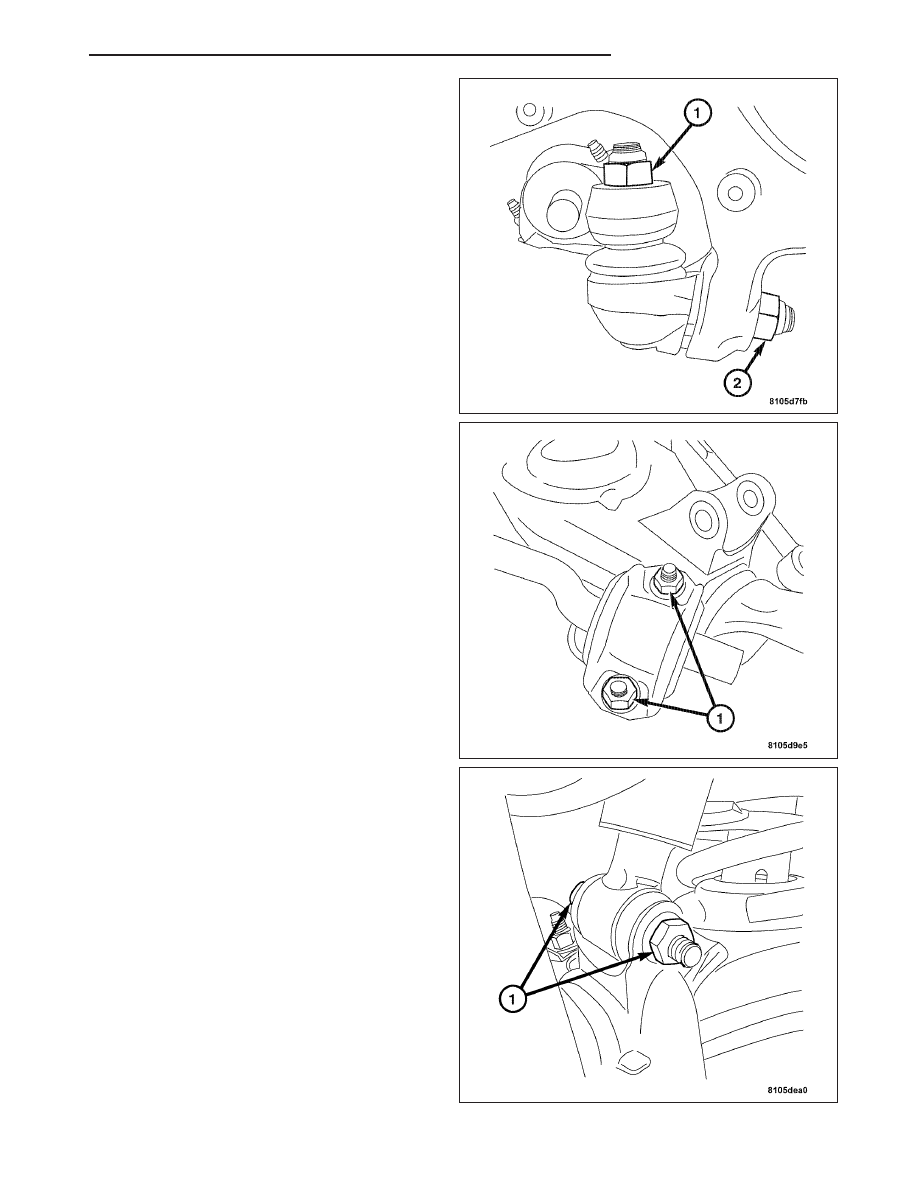
3. Install the nut (2) attaching the lower control arm to

the steering knuckle lower ball joint. Tighten to 45
N·m (33 ft. lbs.).

4. Install the sway bar clamp and bolts (1) to the

lower control arm. Tighten to 20 N·m (15 ft. lbs.).

5. Install the shock absorber bolt and nut (1) to the

lower control arm. Tighten to 55 N·m (41 ft. lbs.).

ZH

FRONT SUSPENSION

2 - 35

6. Install the front spring (1). (Refer to 2 - SUSPEN-

SION/FRONT/SPRING - INSTALLATION).

7. Lower the vehicle and check vehicle alignment.

(Refer to 2 - SUSPENSION/WHEEL ALIGNMENT -
STANDARD PROCEDURE).

8. Install the front wheel and tire assembly. (Refer to

22

- TIRES/WHEELS

-

STANDARD

PROCE-

DURE).

UPPER CONTROL ARM

REMOVAL

Note: If servicing the right upper control arm,
remove the air cleaner housing to access the bolt
and nut.

Note: To remove the upper control arm the shock
absorber must remain installed.

1. Raise and support the vehicle.

2. Remove the front wheel and tire assembly.

3. Wire tie the steering knuckle to the shock absorber

(arrow). This is to hold the steering knuckle from
falling away from the vehicle.

4. Remove the ball joint nut (3) from the upper control

arm (2).

CAUTION: Do not subject the brake hose or any
wheel speed sensor harness to any tension.

CAUTION: Do not use pneumatic tools to tighten the bolt on the tool.

5. Using Special Tool 9168 Ball Joint Puller, press the upper ball joint out of the steering knuckle.

6. Remove the upper control arm (2) from the body by removing the nut and bolt (1) from the inside of the engine

compartment on the shock tower.

2 - 36

FRONT SUSPENSION

ZH

INSTALLATION

WARNING: TIGHTEN ALL NUTS AND BOLTS WITH
THE VEHICLE AT NORMAL RIDE HEIGHT.

1. Install the upper control arm (2) and the bolt and

nut (1) to the body. Tighten to 65 N·m (48 ft. lbs.)

Note: Clean the ball joint tapered bolt and mount-
ing hole of the steering knuckle.

2. Install the upper ball joint (3) to the steering

knuckle. Tighten to 45 N·m (33 ft. lbs.)

3. Remove the wire tie attaching the steering knuckle

to the shock absorber.

4. Lower the vehicle and check vehicle alignment.

(Refer to 2 - SUSPENSION/WHEEL ALIGNMENT -
STANDARD PROCEDURE).

5. Install the wheel and tire assembly. (Refer to 22 -

TIRES/WHEELS - STANDARD PROCEDURE).

SHOCK

REMOVAL

Note: The vehicle must be standing on its wheels
when removing the upper shock absorber mount-
ing nut.

1. Remove the shock absorber upper mounting nut

(1).

2. Remove the washer and rubber mounts.

3. Raise and support the vehicle.

ZH

FRONT SUSPENSION

2 - 37

4. Remove the shock absorber nut and bolt (1) from

the lower control arm. Then remove the shock from
the vehicle by pulling it down and out of the vehi-
cle.

5. Remove any mounting parts from the shock

absorber.

6. Inspect all mounting parts for any damage or

cracks.

INSTALLATION

1. Install the mounting hardware and bushings to the

lower mount and the shock absorber upper mount-
ing stud.

2. Install the shock absorber to the vehicle by insert-

ing the top first and then aligning the lower control
arm mounting bracket to the shock absorber.

3. Install the shock absorber lower bolt and nut (1) to

the lower control arm. Tighten to 55 N·m (41 ft.
lbs.).

4. Slowly lower the vehicle making sure to guide the

upper shock stud through the mounting hole.

5. Install the rubber mount and washer over the shock

absorber stud.

6. Install the shock absorber upper mounting nut (1).

Tighten to 18 N·m (13 ft. lbs.).

7. Lower the vehicle and check vehicle alignment.

(Refer to 2 - SUSPENSION/WHEEL ALIGNMENT -
STANDARD PROCEDURE).

2 - 38

FRONT SUSPENSION

ZH


Content   ..  13  14  15  16   ..