Chrysler 300/300 Touring/300C, Dodge Magnum. Manual - part 778


  Index      Chrysler     Chrysler 300/300 Touring/300C, Dodge Magnum - service repair manual


Search            


Content   ..  776  777  778  779   ..


Chrysler 300/300 Touring/300C, Dodge Magnum. Manual - part 778


When Monitored:
During the VTSS pre-arm process.

Set Condition:
The Intrusion Transceiver Module detects a short to battery condition on the sensor ground circuit.

Possible Causes

(G945) INTRUSION TRANSMITTER SENSOR GROUND CIRCUIT SHORTED TO BATTERY

(G946) INTRUSION RECEIVER SENSOR GROUND CIRCUIT SHORTED TO BATTERY

INTRUSION TRANSCEIVER MODULE

Diagnostic Test

1.

DETERMINING IF DTC IS CURRENT

NOTE: Diagnose any related Communication DTC(s) before continuing.
With a scan tool, read and record DTC(s).

With the scan tool, clear DTC(s).

Turn the ignition off and remove the key from the ignition.

Lock and close all doors to allow the VTSS to go from pre-arm to armed status and wait one minute.

Disarm the VTSS.

Using the scan tool, read DTC(s).

Does the DTC reset?

Yes

>> Go to 2

No

>> DTC is not active at this time. Test complete.

Perform BODY VERIFICATION TEST – VER 1 (Refer to 8 - ELECTRICAL/ELECTRONIC CONTROL
MODULES - STANDARD PROCEDURE)

2.

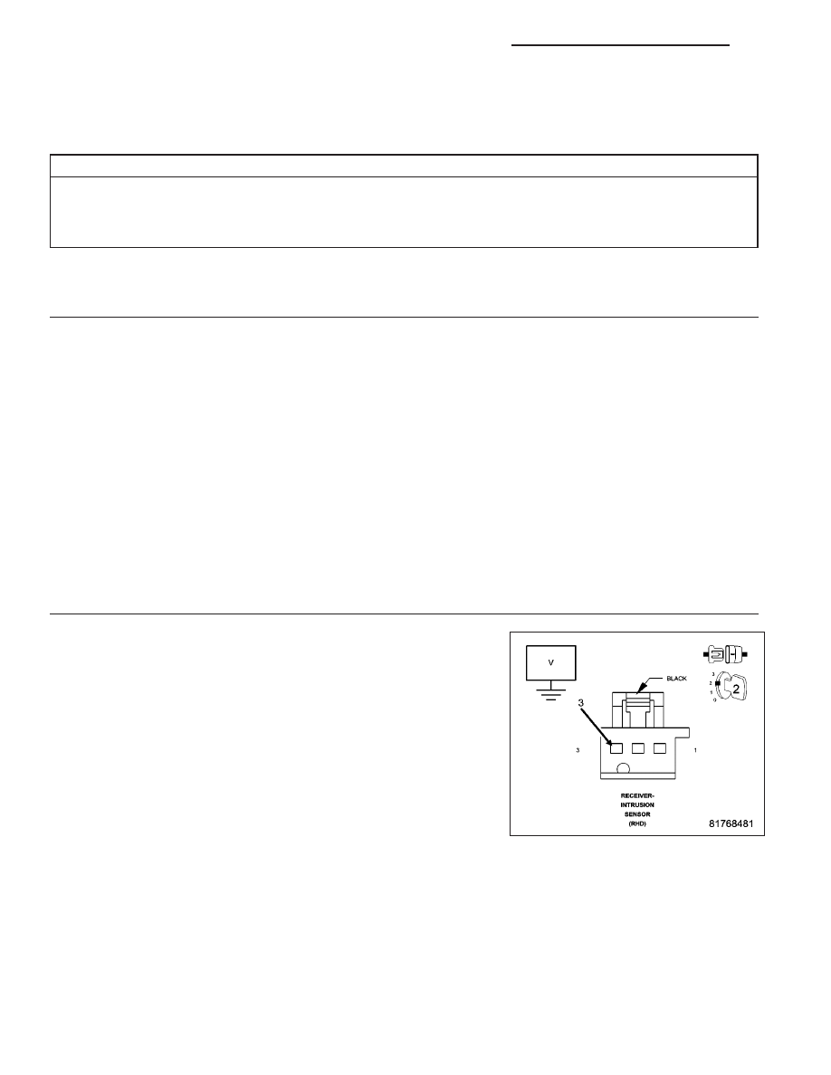
CHECK THE (G946) INTRUSION RECEIVER SENSOR GROUND CIRCUIT SHORT TO BATTERY

Turn the ignition off.

Disconnect the Intrusion Sensor Receiver connector.

Disconnect the Intrusion Transceiver Module connector.

Turn the ignition on.

Measure the voltage of the (G946) Intrusion Receiver Sensor Ground
circuit in the Intrusion Sensor Receiver connector.

Is there any voltage present?

Yes

>> Repair the (G946) Intrusion Receiver Sensor Ground circuit

for a short to voltage.

Perform BODY VERIFICATION TEST – VER 1 (Refer to 8 -
ELECTRICAL/ELECTRONIC

CONTROL

MODULES

-

STANDARD PROCEDURE)

No

>> Go To 3

8Q - 80

VEHICLE THEFT SECURITY - ELECTRICAL DIAGNOSTICS

LX

3.

CHECK THE (G945) SENSOR GROUND CIRCUIT SHORT TO BATTERY

Turn the ignition off.

Disconnect the Intrusion Sensor Transmitter connector.

Turn the ignition on.

Measure the voltage of the (G945) Intrusion Transmitter Sensor Ground
circuit in the Intrusion Sensor Transmitter connector.

Is there any voltage present?

Yes

>> Repair the (G945) Transmitter Sensor Ground circuit for a

short to voltage.

Perform BODY VERIFICATION TEST – VER 1 (Refer to 8 -
ELECTRICAL/ELECTRONIC

CONTROL

MODULES

-

STANDARD PROCEDURE)

No

>> Replace the Intrusion Transceiver Module in accordance

with the Service Information.

Perform BODY VERIFICATION TEST – VER 1 (Refer to 8 - ELECTRICAL/ELECTRONIC CONTROL
MODULES - STANDARD PROCEDURE)

LX

VEHICLE THEFT SECURITY - ELECTRICAL DIAGNOSTICS

8Q - 81

B2101-IGNITION RUN/START INPUT LOW

For a complete wiring diagram Refer to Section 8W.

8Q - 82

VEHICLE THEFT SECURITY - ELECTRICAL DIAGNOSTICS

LX

When Monitored:
With the ignition switch on.

Set Condition:
The SKREEM has detected the ignition switch input voltage below a calibrated value.

Possible Causes

FUSED IGNITION SWITCH OUTPUT (RUN-START) CIRCUIT OPEN

SKREEM

Diagnostic Test

1.

DETERMINING IF DTC IS CURRENT

NOTE: Diagnose any related Powertrain DTC(s) before continuing.
With a scan tool, read and record DTC(s).

With the scan tool, clear DTC(s).

Perform 5 ignition cycles, leaving the ignition switch on for a minimum of 90 seconds per cycle.

Using the scan tool, read DTC(s).

Does the DTC reset?

Yes

>> Go To 3

No

>> Go to 2

2.

INTERMITTENT CONDITION

NOTE: Check for any of the follow conditions:

Poor wire to terminal connection

Corroded terminals

Backed out or loose terminals

Broken wire internal to the insulation

Dirty (partial) module ground

With the ignition on, wiggle the related wires.

Using a scan tool, read DTC(s).

Does the DTC reset?

Yes

>> Repair the wiring as necessary.

Perform SKREEM VERIFICATION TEST.

No

>>

DTC is not active at this time. Test complete.

3.

FUSED IGNITION SWITCH OUTPUT (RUN-START) CIRCUIT OPENED

NOTE: Check the related fuses to the Fused Ignition Switch Output (Run-Start) circuit. If the fuse is found
to be open, repair the circuit for a shorted condition.
Turn the ignition off.

Disconnect the SKREEM harness connector.

Turn the ignition on.

Using a 12 volt test light connected to ground, probe the Fused Ignition Switch Output (Run-Start) circuit in the
SKREEM harness connector.

Does the test light illuminate brightly?

Yes

>> Go to 4

No

>> Repair the Fused Ignition Switch Output (Run-Start) circuit for an open.

Perform SKREEM VERIFICATION TEST.

LX

VEHICLE THEFT SECURITY - ELECTRICAL DIAGNOSTICS

8Q - 83


Content   ..  776  777  778  779   ..