Chrysler 300/300 Touring/300C, Dodge Magnum. Manual - part 747
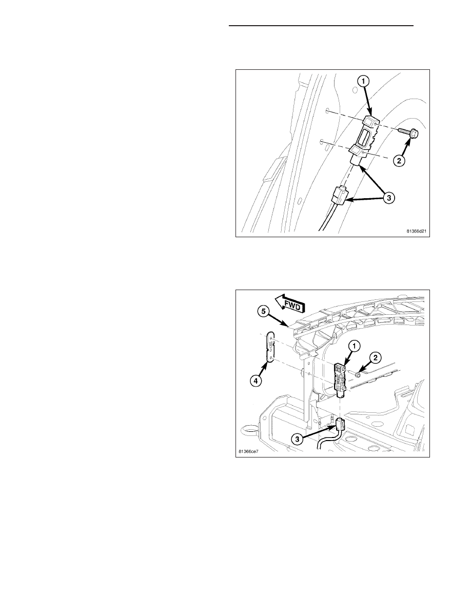
C-PILLAR MOUNTED SIDE IMPACT SENSOR
1. Disconnect and isolate the battery negative cable.
WARNING: Wait two minutes for the airbag system
reserve capacitor to discharge before beginning
any airbag system or component service. Failure
to do so may result in accidental airbag deploy-
ment, personal injury or death.
2. Remove the C-pillar trim panel (Refer to 23 -
BODY/INTERIOR/C-PILLAR TRIM - REMOVAL).
3. Disconnect the electrical connector (3).
4. Remove the two retaining screws (2).
INSTALLATION
FRONT IMPACT SENSOR
1. Position the front impact sensor in the correct
mounting location and install the two mounting
screws (2). Torque screws (2) to 7 N·m (62 in. lbs.).
2. Connect the electrical connector (3).
NOTE: If replacing the left front impact sensor, the
air intake system needs to be installed (Refer to 9
- ENGINE/AIR INTAKE SYSTEM - INSTALLATION).
WARNING: Do not connect the battery negative
cable (Refer to 8 - ELECTRICAL/RESTRAINTS -
DIAGNOSIS AND TESTING - AIRBAG SYSTEM).
Personal injury or death may result if the system
test is not performed first.
8O - 394
RESTRAINTS - SERVICE INFORMATION
LX