Chrysler 300/300 Touring/300C, Dodge Magnum. Manual - part 744


  Index      Chrysler     Chrysler 300/300 Touring/300C, Dodge Magnum - service repair manual


Search            


Content   ..  742  743  744  745   ..


Chrysler 300/300 Touring/300C, Dodge Magnum. Manual - part 744


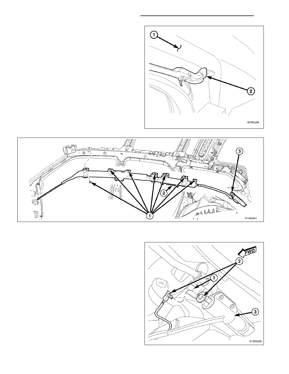
3. Clip the front tether (2) to the A-pillar (1) and install

push fastener.

4. Install the screws (1) that secure the curtain airbag to the spring nuts in the roof side rail. Torque screws to 5

N·m (44 in. lbs.).

5. Connect the curtain airbag squib connector (2) to

the inflator (3).

6. Install the headliner into the vehicle (Refer to 23 -

BODY/INTERIOR/HEADLINER - INSTALLATION).

WARNING: Do not connect the battery negative
cable (Refer to 8 - ELECTRICAL/RESTRAINTS -
DIAGNOSIS AND TESTING - AIRBAG SYSTEM).
Personal injury or death may result if the system
test is not performed first.

8O - 382

RESTRAINTS - SERVICE INFORMATION

LX

DRIVER AIRBAG

DESCRIPTION

The driver airbag used in this model is a multistage,
Next Generation-type that complies with revised fed-
eral airbag standards to deploy with less force than
those used in some prior models. A radial deploying
fabric cushion with internal tethers is used. The airbag
inflator is a dual-initiator, non-azide, pyrotechnic-type
unit with four mounting studs and is secured to the
stamped metal airbag housing by four flanged hex
nuts. Two keyed and color-coded connector recepta-
cles on the driver airbag inflator connect the two infla-
tor initiators to the vehicle electrical system through
two yellow-jacketed, two-wire pigtail harnesses of the
clockspring.

The driver airbag unit cannot be repaired, and must
be replaced if deployed or in any way damaged. The
driver airbag trim cover and horn switch unit may be
disassembled from the driver airbag unit, and is avail-
able for separate service replacement.

The driver airbag protective trim cover (1) is the most
visible part of the driver airbag. The driver airbag is
located in the center of the steering wheel (1), where
it is secured with two screws to the armature of the
four-spoke steering wheel. Concealed beneath the
driver airbag trim cover are the horn switch, the folded
airbag cushion, the airbag cushion retainer, the airbag
housing, the airbag inflator, and the retainers that
secure the inflator to the airbag housing.

The airbag cushion, housing, and inflator are secured
within the trim cover.

LX

RESTRAINTS - SERVICE INFORMATION

8O - 383

The vertical walls of this trim cover have small win-
dows with blocking tabs that are engaged by hook for-
mations around the perimeter of the airbag housing.
Each hook is inserted through one of the windows and
the blocking tab in each window keeps the hook prop-
erly engaged with the trim cover, locking the trim
cover securely into place on the airbag housing.

The resistive membrane-type horn switch is secured
with heat stakes to the inside surface of the driver air-
bag trim cover, between the trim cover and the folded
airbag cushion.

OPERATION

The multistage driver airbag is deployed by electrical signals generated by the Occupant Restraint Controller (ORC)
through the driver airbag squib 1 and squib 2 circuits to the two initiators in the airbag inflator. By using two initi-
ators, the airbag can be deployed at multiple levels of force. The force level is controlled by the ORC to suit the
monitored impact conditions by providing one of three delay intervals between the electrical signals provided to the
two initiators. The longer the delay between these signals, the less forcefully the airbag will deploy.

When the ORC sends the proper electrical signals to each initiator, the electrical energy generates enough heat to
initiate a small pyrotechnic charge which, in turn ignites chemical pellets within the inflator. Once ignited, these
chemical pellets burn rapidly and produce a large quantity of inert gas. The inflator is sealed to the back of the
airbag housing and a diffuser in the inflator directs all of the inert gas into the airbag cushion, causing the cushion
to inflate. As the cushion inflates, the driver airbag trim cover will split at predetermined breakout lines, then fold
back out of the way along with the horn switch unit. Following an airbag deployment, the airbag cushion quickly
deflates by venting the inert gas towards the instrument panel through vent holes within the fabric used to construct
the back (steering wheel side) panel of the airbag cushion.

Some of the chemicals used to create the inert gas may be considered hazardous while in their solid state before
they are burned, but they are securely sealed within the airbag inflator. Typically, both initiators are used and all
potentially hazardous chemicals are burned during an airbag deployment event.

The inert gas that is produced when the chemicals are burned is harmless. However, a small amount of residue
from the burned chemicals may cause some temporary discomfort if it contacts the skin, eyes, or breathing pas-
sages. If skin or eye irritation is noted, rinse the affected area with plenty of cool, clean water. If breathing passages
are irritated, move to another area where there is plenty of clean, fresh air to breath. If the irritation is not alleviated
by these actions, contact a physician.

8O - 384

RESTRAINTS - SERVICE INFORMATION

LX

REMOVAL

1. Disconnect and isolate the battery negative cable.

WARNING: Wait two minutes for the airbag system
reserve capacitor to discharge before beginning
any airbag system or component service. Failure
to do so may result in accidental airbag deploy-
ment, personal injury or death.

2. From behind the steering wheel (1), remove the

two screw covers and screws (5) to the driver air-
bag (3).

CAUTION: Do not pull on the horn switch feed pig-
tail wire to disengage the connector from the
driver airbag or to disconnect the horn switch to
steering wheel wire harness connection. Improper
pulling on this pigtail wire or connection can
result in damage to the horn switch membrane or
feed circuit.

3. Carefully pull airbag rearward just far enough to disconnect the two airbag squib connectors (2) and the horn

connector (4).

4. Separate driver airbag from steering column.

NOTE: The driver airbag trim cover is available for service separately. If the horn switch is faulty or the trim
cover is damaged, the airbag cushion assembly may be transferred to a new trim cover. If the airbag is
defective, the entire driver airbag and driver airbag trim cover must be replaced as an assembly.

INSTALLATION

NOTE: The driver airbag trim cover is available for
service separately. If the horn switch is faulty or
the trim cover is damaged, the airbag cushion
assembly may be transferred to a new trim cover.
If the airbag is defective, the entire driver airbag
and driver airbag trim cover must be replaced as
an assembly.

1. Position driver airbag (3) in steering wheel (1) near

mounting location.

2. Connect the two airbag squib connectors (2) and

the horn connector (4).

3. Position the driver airbag mounting screws (2) into

the driver airbag. From behind the steering wheel
(1) install the two screws (5) to the driver airbag.
Torque the two screws (5) to 10 N·m (89 in. lbs.).

WARNING: Do not connect the battery negative
cable (Refer to 8 - ELECTRICAL/RESTRAINTS -
DIAGNOSIS AND TESTING - AIRBAG SYSTEM). Personal injury or death may result if the system test is not
performed first.

LX

RESTRAINTS - SERVICE INFORMATION

8O - 385


Content   ..  742  743  744  745   ..