Chrysler 300/300 Touring/300C, Dodge Magnum. Manual - part 593


  Index      Chrysler     Chrysler 300/300 Touring/300C, Dodge Magnum - service repair manual


Search            


Content   ..  591  592  593  594   ..


Chrysler 300/300 Touring/300C, Dodge Magnum. Manual - part 593


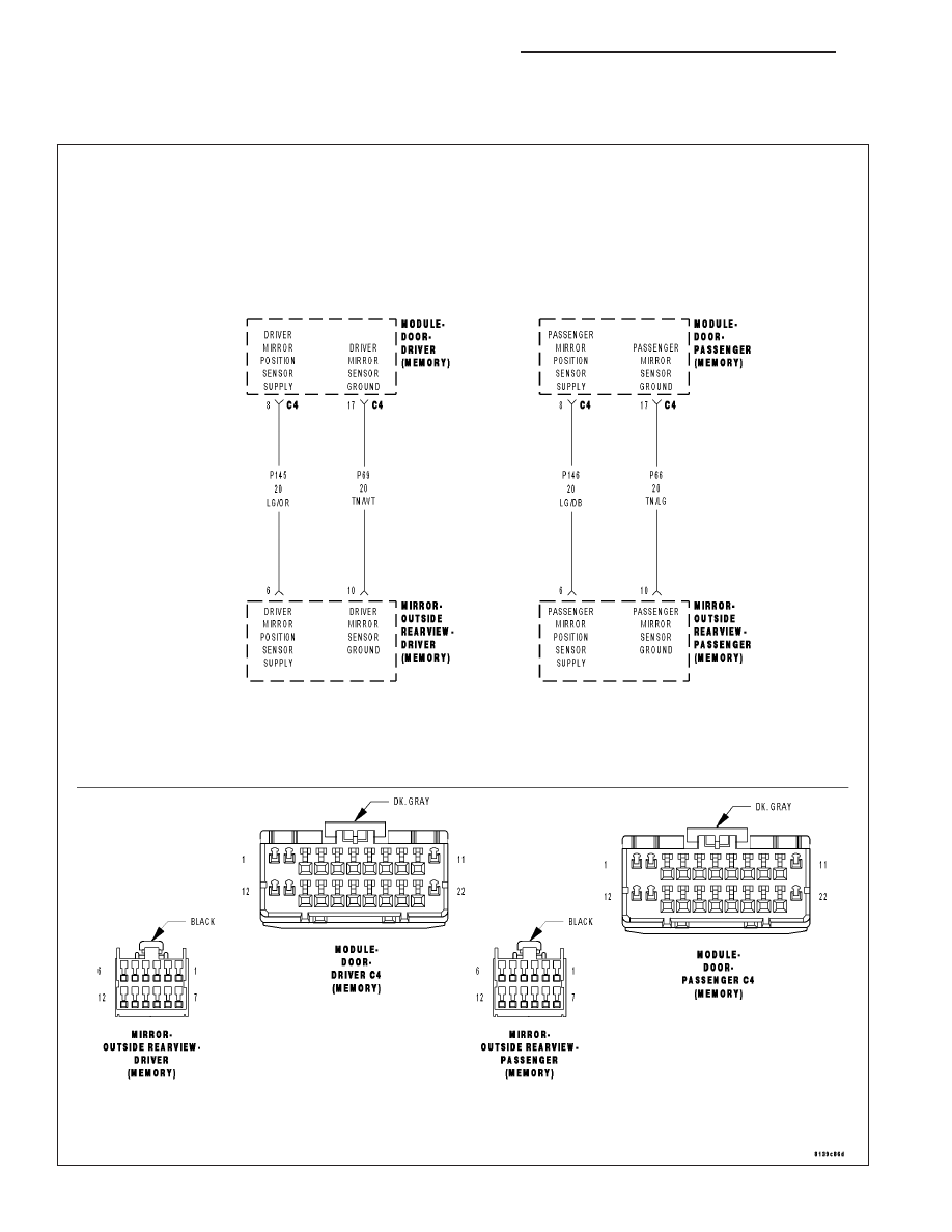
B1D0A,B1D13–MIRROR POSITION SENSOR POWER SUPPLY CIRCUIT HIGH –
DOOR MODULE

8N - 70

POWER MIRRORS - ELECTRICAL DIAGNOSTICS

LX

For a complete wiring diagram Refer to Section 8W.

When Monitored:
Continuously.

Set Condition:
When the Driver/Passenger Door Module senses voltage above 5.5 volts on the Mirror Position Sensor Supply
circuit for over 30 ms., this code will set.NOTE: This test covers both the Driver and Passenger code
depending on the side the code appeared in.

Possible Causes

(P145) OR (P146) MIRROR POSITION SENSOR SUPPLY CIRCUIT OPEN

(P145) OR (P146) MIRROR POSITION SENSOR SUPPLY CIRCUIT SHORT TO VOLTAGE

(P69) R (P66) MIRROR SENSOR GROUND CIRCUIT OPEN

MIRROR OPEN

DRIVER/PASSENGER DOOR MODULE

Diagnostic Test

1.

TEST FOR INTERMITTENT CONDITION

Turn the ignition on.

With the scan tool, record and erase DTC’s

Operate the Mirror Switch in all directions several times.

Cycle the ignition from on to off three times.

Turn the ignition on.

With the scan tool, read DTC’s.

Does the scan tool display B1D0A or B1d13–MIRROR POSITION SENSOR POWER SUPPLY CIRCUIT
HIGH?

Yes

>> Go To 2

No

>> The conditions that caused this code to set are not present at this time. Using the wiring diagram/sche-

matic as a guide, inspect the wiring and connectors.

Perform BODY VERIFICATION TEST - VER 1. (Refer to BODY VERIFICATION TEST - VER 1).

LX

POWER MIRRORS - ELECTRICAL DIAGNOSTICS

8N - 71

2.

TEST FOR AN OPEN MIRROR

Turn the ignition off.

Disconnect the appropriate mirror connector.

Turn the ignition on.

Measure the voltage between the (P145) or (P146) Mirror Position Sen-
sor Supply circuit and the ((P69) or (P66) Mirror Sensor Ground circuit.

Is the voltage between 4.8 and 5.2 volts?

Yes

>> Replace the Mirror.

Perform BODY VERIFICATION TEST - VER 1. (Refer to
BODY VERIFICATION TEST - VER 1).

No

>> Go to 3

3.

TEST THE (P145) OR (P146) MIRROR POSITION SENSOR SUPPLY WIRE FOR AN OPEN

Turn the ignition off.

Disconnect the appropriate Door Module C4 connector.

Measure the resistance between of the (P145) or (P146) Mirror Position
Sensor Supply circuit between the Module connector and the Mirror
connector.

Is the resistance below 2.0 ohms?

No

>> Repair the (P145) or (P146) Mirror Position Sensor Supply

circuit for an open.

Perform BODY VERIFICATION TEST - VER 1. (Refer to
BODY VERIFICATION TEST - VER 1).

Yes

>> Go to 4

8N - 72

POWER MIRRORS - ELECTRICAL DIAGNOSTICS

LX

4.

TEST THE (P69) OR (P66) MIRROR SENSOR GROUND WIRE FOR AN OPEN

Measure the resistance of the ((P69) or (P66) Mirror Sensor Ground
circuit between the Module connector and the Mirror connector.

Is the resistance below 2.0 ohms?

No

>> Repair the (P69) or (P66) Mirror Sensor Ground circuit for

an open.

Perform BODY VERIFICATION TEST - VER 1. (Refer to
BODY VERIFICATION TEST - VER 1).

Yes

>> Go to 5

Perform BODY VERIFICATION TEST - VER 1. (Refer to
BODY VERIFICATION TEST - VER 1).

5.

TEST THE (P145) OR (P146) MIRROR POSITION SENSOR SUPPLY WIRE SHORTED TO VOLTAGE

Turn the ignition on.

Measure the voltage between ground and the (P145) or (P146) Mirror
Position Sensor Supply circuit.

Is there any voltage present?

Yes

>> Repair the (P145) or (P146) Mirror Position Sensor Supply

circuit for a short to voltage.

Perform BODY VERIFICATION TEST - VER 1. (Refer to
BODY VERIFICATION TEST - VER 1).

No

>> Replace the appropriate Door Module.

Perform BODY VERIFICATION TEST - VER 1. (Refer to
BODY VERIFICATION TEST - VER 1).

LX

POWER MIRRORS - ELECTRICAL DIAGNOSTICS

8N - 73


Content   ..  591  592  593  594   ..