Chrysler 300/300 Touring/300C, Dodge Magnum. Manual - part 575


  Index      Chrysler     Chrysler 300/300 Touring/300C, Dodge Magnum - service repair manual


Search            


Content   ..  573  574  575  576   ..


Chrysler 300/300 Touring/300C, Dodge Magnum. Manual - part 575


SENSOR-AMBIENT AIR TEMPERATURE
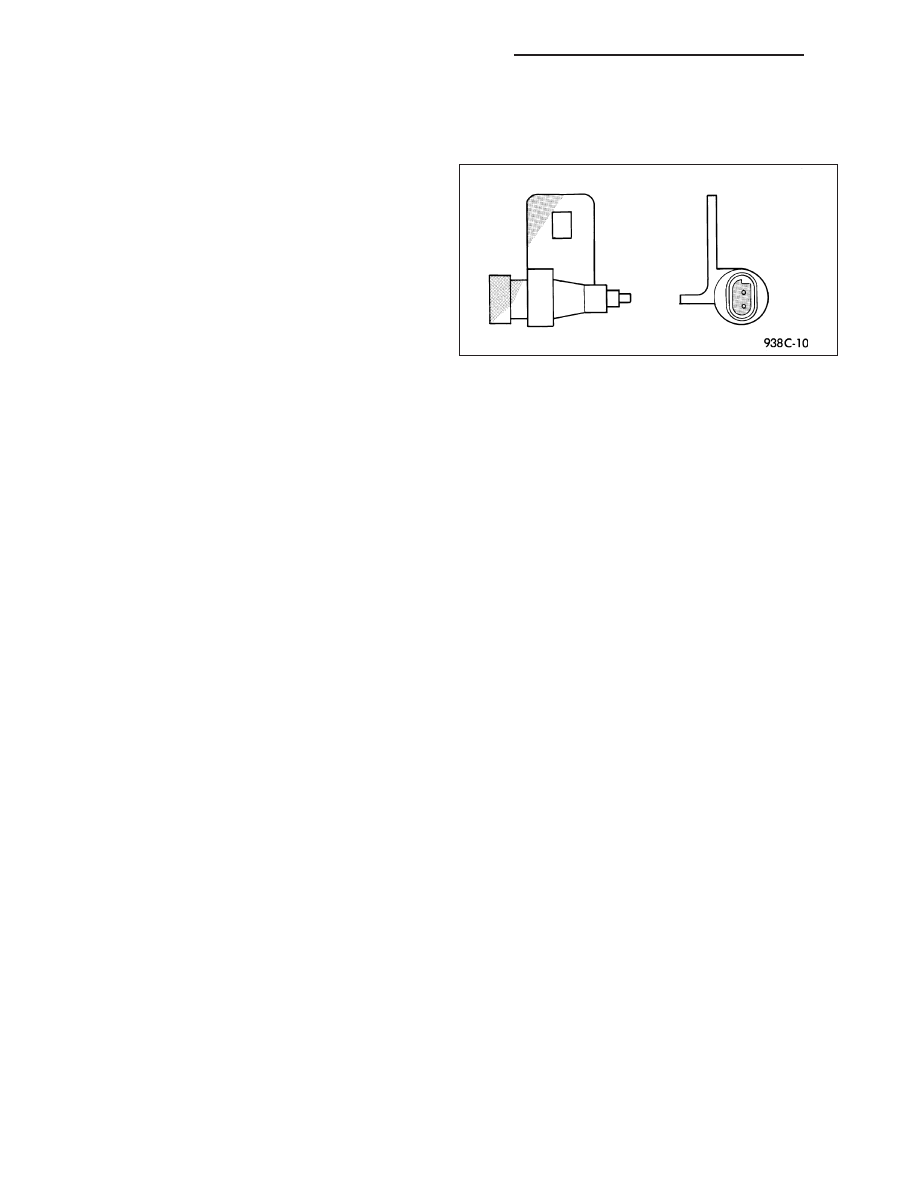
DESCRIPTION

The ambient temperature sensor is a variable resistor
type sensor. it is mounted to the lower front fascia
behind the radiator grille and in front of the engine
compartment.

The ambient temperature sensor cannot be adjusted
or repaired and, if inoperative or damaged, it must be
replaced.

OPERATION

The ambient temperature sensor is a variable resistor that operates on a five-volt reference signal sent by the Front
Control Module (FCM). The resistance in the sensor changes as temperature changes, changing the temperature
sensor signal circuit voltage to the FCM. Based upon the resistance in the sensor, the FCM senses a specific volt-
age on the temperature sensor signal circuit. The FCM then translates the voltage into a temperature reading that
it sent over the Controller Area Network (CAN) data bus to other modules utilizing temperature information.

DIAGNOSIS AND TESTING

AMBIENT TEMPERATURE SENSOR

The temperature function is supported by the ambient temperature sensor, a wiring circuit, and the Front Control
Module (FCM). If any portion of the ambient temperature sensor circuit fails or if the Controller Area Network (CAN)
data bus information is missing, a (– –) will appear in the Electronic Vehicle Information Center (EVIC) display in
place of the temperature. When the sensor is exposed to temperatures above 55° C (130° F), or if the sensor circuit
is shorted, 55° C (130° F) will appear in the EVIC display in place of the temperature. When the sensor is exposed
to temperatures below - 40° C (- 40° F) or if the sensor circuit is open, - 40° C (- 40° F) will appear in the EVIC
display.

The ambient temperature sensor circuit can also be diagnosed using the following Sensor Test, and Sensor Circuit
Test. If the temperature sensor and circuit are confirmed to be OK, but the temperature display is inoperative or
incorrect, test the EVIC operation, (Refer to 8 - ELECTRICAL/OVERHEAD CONSOLE/ELECTRONIC VEHICLE
INFO CENTER - DIAGNOSIS AND TESTING).

SENSOR TEST

1. Turn the ignition switch to the Off position. Disconnect and isolate the battery negative cable. Disconnect the

ambient temperature sensor harness connector.

2. Measure the resistance of the ambient temperature sensor. At - 40° C (- 40° F), the sensor resistance is 336

kilohms. At 55° C (130° F), the sensor resistance is 2.488 kilohms. The sensor resistance should read between
these two values. If OK, refer to Sensor Circuit Test in this group. If not OK, replace the inoperative ambient
temperature sensor.

SENSOR CIRCUIT TEST

Refer to the appropriate wiring information for complete circuit schematic or connector pin-out information.

1. Turn the ignition switch to the Off position. Disconnect and isolate the battery negative cable. Disconnect the wire

harness connectors from the ambient temperature sensor and the FCM.

2. Connect a jumper wire between the two terminals in the body half of the ambient temperature sensor harness

connector.

3. Check for continuity between the sensor return circuit and the ambient temperature sensor signal circuit cavities

of the FCM harness connector. There should be continuity. If OK, go to Step 4. If not OK, repair the open sensor
return circuit or ambient temperature sensor signal circuit to the ambient temperature sensor as required.

8M - 170

OVERHEAD CONSOLE - SERVICE INFORMATION

LX

4. Check for continuity between the ambient temperature sensor signal circuit cavity of the FCM harness connector

and a good ground. There should be no continuity. If OK, test the EVIC operation, (Refer to 8 - ELECTRICAL/
OVERHEAD CONSOLE/ELECTRONIC VEHICLE INFO CENTER - DIAGNOSIS AND TESTING). If not OK,
repair the shorted ambient temperature sensor signal circuit as required.

REMOVAL

1. Disconnect and isolate the battery negative cable.

2. Remove the belly pan, (Refer to 23 - BODY/EXTERIOR/BELLY PAN - REMOVAL).

3. Disconnect the wire harness connector (1) from the

ambient temperature sensor (2).

4. Remove the fastener that secures the ambient tem-

perature sensor bracket to the front fascia.

5. Remove the ambient temperature sensor from the

vehicle.

LX

OVERHEAD CONSOLE - SERVICE INFORMATION

8M - 171

INSTALLATION

1. Position the ambient temperature sensor in the

vehicle.

2. Install the fastener that secures the ambient tem-

perature sensor to the front fascia.

3. Connect the wire harness connector (1) to the

ambient temperature sensor (2).

4. Install the belly pan, (Refer to 23 - BODY/EXTERI-

OR/BELLY PAN - INSTALLATION).

5. Connect the battery negative cable.

8M - 172

OVERHEAD CONSOLE - SERVICE INFORMATION

LX

POWER SYSTEMS

TABLE OF CONTENTS

page

page

POWER LOCKS - ELECTRICAL DIAGNOSTICS. . . . 1
POWER LOCKS - SERVICE INFORMATION . . . . . 50
POWER MIRRORS - ELECTRICAL

DIAGNOSTICS . . . . . . . . . . . . . . . . . . . . . . . . . . 58

POWER MIRRORS - SERVICE INFORMATION . . 114
POWER SEATS - ELECTRICAL DIAGNOSTICS . . 119

POWER SEATS - SERVICE INFORMATION. . . . . 184
POWER TOP - ELECTRICAL DIAGNOSIS . . . . . . 201
POWER TOP - SUNROOF SERVICE INFO . . . . . 220
POWER WINDOWS - ELECTRICAL

DIAGNOSTICS . . . . . . . . . . . . . . . . . . . . . . . . . 228

POWER WINDOWS - SERVICE INFORMATION . 290

POWER LOCKS - ELECTRICAL DIAGNOSTICS

TABLE OF CONTENTS

page

page

POWER LOCKS - ELECTRICAL DIAGNOSTICS

DIAGNOSIS AND TESTING

B1801–DRIVER DOOR LOCK/UNLOCK

SWITCH CIRCUIT LOW — CLUSTER . . . . . . . . . 3

B1803–DRIVER DOOR LOCK/UNLOCK

SWITCH CIRCUIT STUCK LOCK—
CLUSTER . . . . . . . . . . . . . . . . . . . . . . . . . . . . . . . . . . 6

B1804–DRIVER DOOR LOCK/UNLOCK

SWITCH CIRCUIT STUCK UNLOCK—
CLUSTER . . . . . . . . . . . . . . . . . . . . . . . . . . . . . . . . . . 9

B1806–PASSENGER DOOR LOCK/UNLOCK

SWITCH CIRCUIT LOW — CLUSTER . . . . . . . . 12

B1808–PASSENGER DOOR LOCK/UNLOCK

SWITCH CIRCUIT STUCK LOCK —
CLUSTER . . . . . . . . . . . . . . . . . . . . . . . . . . . . . . . . . 15

B1809–PASSENGER DOOR LOCK/UNLOCK

SWITCH CIRCUIT STUCK UNLOCK —
CLUSTER . . . . . . . . . . . . . . . . . . . . . . . . . . . . . . . . . 18

B1826–TRUNK RELEASE SWITCH INPUT

CIRCUIT LOW . . . . . . . . . . . . . . . . . . . . . . . . . . . . . 21

*DECKLID/LIFTGATE RELEASE

INOPERATIVE . . . . . . . . . . . . . . . . . . . . . . . . . . . . . 24

*ALL DOORS FAIL TO LOCK . . . . . . . . . . . . . . . . . 32
*PASSENGER DOORS FAIL TO UNLOCK . . . . . 35
*RIGHT DOOR LOCKS INOPERATIVE –

(LHD ONLY) . . . . . . . . . . . . . . . . . . . . . . . . . . . . . . . 37

*LEFT DOOR LOCKS INOPERATIVE – (LHD

ONLY) . . . . . . . . . . . . . . . . . . . . . . . . . . . . . . . . . . . . 40

*DRIVER DOOR LOCK INOPERATIVE . . . . . . . . 43
*ONE PASSENGER DOOR LOCK

INOPERATIVE . . . . . . . . . . . . . . . . . . . . . . . . . . . . . 46

LX

POWER SYSTEMS

8N - 1


Content   ..  573  574  575  576   ..