Chrysler 300/300 Touring/300C, Dodge Magnum. Manual - part 409


  Index      Chrysler     Chrysler 300/300 Touring/300C, Dodge Magnum - service repair manual


Search            


Content   ..  407  408  409  410   ..


Chrysler 300/300 Touring/300C, Dodge Magnum. Manual - part 409


between the battery positive cable terminal clamp and the battery positive terminal post.

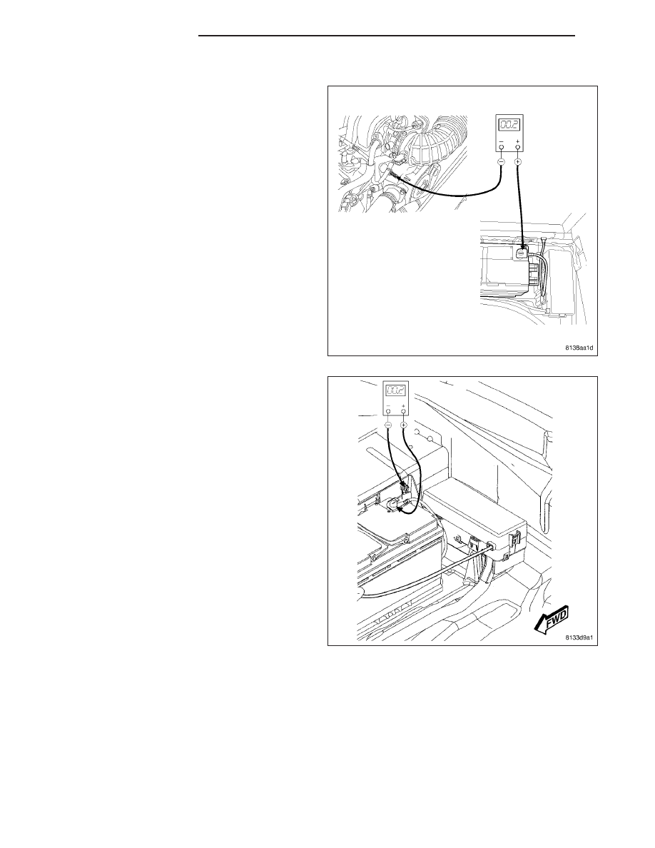
3. Using a suitable jumper wire, connect the voltmeter

to measure between the battery negative cable ter-
minal clamp and a good clean ground on the
engine block. Rotate and hold the ignition switch in
the Start position. Observe the voltmeter. If the
reading is above 0.2 volt, clean and tighten the bat-
tery negative cable eyelet terminal connection at
the transmission housing. Repeat the test. If the
reading is still above 0.2 volt, perform Step 4 and
Step 5.

4. Connect the voltmeter to measure between the bat-

tery negative cable terminal clamp and the battery
negative cable eyelet terminal connection at the
vehicle body. Rotate and hold the ignition switch in
the Start position. Observe the voltmeter. If the
reading is above 0.2 volt, clean and tighten the bat-
tery negative cable eyelet terminal connection at
the vehicle body. Repeat the test. If the reading is
still above 0.2 volt, replace the battery rear nega-

8F - 22

BATTERY SYSTEM

LX

tive cable, (Refer to 8 - ELECTRICAL/BATTERY SYSTEM/CABLES - REMOVAL).

5. Connect the voltmeter to measure between the bat-

tery negative cable eyelet terminal connection at
the right front strut tower and the battery negative
cable eyelet terminal connection at the transmis-
sion housing. Rotate and hold the ignition switch in
the Start position. Observe the voltmeter. If the
reading is above 0.2 volt, clean and tighten the bat-
tery negative cable eyelet terminal connection at
the right front strut tower. Repeat the test. If the
reading is still above 0.2 volt, replace the battery

LX

BATTERY SYSTEM

8F - 23

front negative cable, (Refer to 8 - ELECTRICAL/BATTERY SYSTEM/CABLES - REMOVAL).

6. Using a suitable jumper wire, connect the voltmeter

to measure between the battery positive cable ter-
minal clamp and the starter solenoid B(+) terminal
stud. Rotate and hold the ignition switch in the
Start position. Observe the voltmeter. If the reading
is above 0.2 volt, clean and tighten the battery pos-
itive cable eyelet terminal connection at the starter
solenoid B(+) terminal stud. Repeat the test. If the
reading is still above 0.2 volt, perform Step 7 and
Step 8.

7. Remove the right front wheelhouse splash shield to

gain access to the battery positive cable bulkhead
outside terminal, (Refer to 23 - BODY/EXTERI-
OR/RF

WHEELHOUSE

SPLASH

SHIELD

-

REMOVAL). Connect the voltmeter to measure
between the battery positive cable bulkhead out-
side terminal and the starter solenoid B(+) terminal
stud. Rotate and hold the ignition switch in the
Start position. Observe the voltmeter. If the reading
is above 0.2 volt, clean and tighten the battery pos-
itive cable bulkhead outside terminal connection.
Repeat the test. If the reading is still above 0.2
volt, replace the battery front positive cable, (Refer

8F - 24

BATTERY SYSTEM

LX

to 8 - ELECTRICAL/BATTERY SYSTEM/CABLES - REMOVAL).

8. Remove the right front carpet to gain access to the

battery positive cable bulkhead inside terminal.
Connect the voltmeter to measure between the bat-
tery positive cable terminal clamp and the battery
positive cable bulkhead inside terminal connection.
Rotate and hold the ignition switch in the Start
position. Observe the voltmeter. If the reading is
above 0.2 volt, clean and tighten the battery posi-
tive cable bulkhead inside terminal connection.
Repeat the test. If the reading is still above 0.2
volt, replace the battery rear positive cable, (Refer
to 8 - ELECTRICAL/BATTERY SYSTEM/CABLES -
REMOVAL).

REMOVAL

NEGATIVE - ENGINE COMPARTMENT

1. Turn the ignition switch to the Off position. Be cer-

tain that all electrical accessories are turned off.

2. Remove the spare tire cover to gain access to the

battery.

3. Disconnect and isolate the battery negative cable.

4. Remove the fastener securing the battery negative

cable to the right front strut tower.

LX

BATTERY SYSTEM

8F - 25


Content   ..  407  408  409  410   ..