Chrysler 300/300 Touring/300C, Dodge Magnum. Manual - part 407


  Index      Chrysler     Chrysler 300/300 Touring/300C, Dodge Magnum - service repair manual


Search            


Content   ..  405  406  407  408   ..


Chrysler 300/300 Touring/300C, Dodge Magnum. Manual - part 407


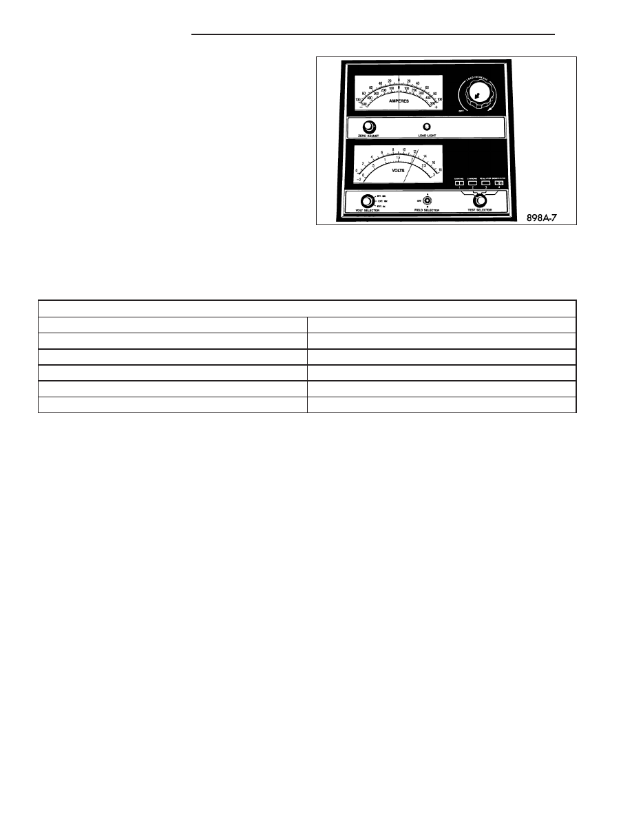
3. Using a voltmeter connected to the battery posts,

measure the open-circuit voltage.

See the Open-Circuit Voltage Table. This voltage reading will indicate the battery state-of-charge, but will not reveal
its cranking capacity. If a battery has an open-circuit voltage reading of 12.4 volts or greater, it may be load tested
to reveal its cranking capacity, (Refer to 8 - ELECTRICAL/BATTERY SYSTEM/BATTERY - STANDARD PROCE-
DURE - USING MICRO 420 BATTERY TESTER).

OPEN CIRCUIT VOLTAGE TABLE

Open Circuit Voltage

Charge Percentage

11.7 volts or less

0%

12.0 volts

25%

12.3 volts

50%

12.6 volts

75%

12.8 volts or more

100%

IGNITION-OFF DRAW TEST

The term Ignition-Off Draw (IOD) identifies a normal condition where power is being drained from the battery with
the ignition switch in the Off position. A normal vehicle electrical system will draw from five to thirty-five milliamperes
(0.005 to 0.035 ampere) with the ignition switch in the Off position, and all non-ignition controlled circuits in proper
working order. Up to thirty-five milliamperes are needed to enable the memory functions for the Powertrain Control
Module (PCM), digital clock, electronically tuned radio, and other modules which may vary with the vehicle equip-
ment.

A vehicle that has not been operated for approximately twenty days, may discharge the battery to an inadequate
level. When a vehicle will not be used for twenty days or more (stored), remove the IOD fuse from the Junction
Block (JB). This will reduce battery discharging.

Excessive IOD can be caused by:

Electrical items left on.

Inoperative or improperly adjusted switches.

Inoperative or shorted electronic modules and components.

An internally shorted generator.

Intermittent shorts in the wiring.

If the IOD is over thirty-five milliamperes, the problem must be found and corrected before replacing a battery. In
most cases, the battery can be charged and returned to service after the excessive IOD condition has been cor-
rected.

1. Verify that all electrical accessories are off. Turn off all lamps, remove the ignition key, and close all doors. If the

vehicle is equipped with an illuminated entry system or an electronically tuned radio, allow the electronic timer
function of these systems to automatically shut off (time out). This may take up to three minutes. See the Elec-
tronic Module Ignition-Off Draw Table for more information.

8F - 14

BATTERY SYSTEM

LX

ELECTRONIC MODULE IGNITION-OFF DRAW (IOD) TABLE

Module

Time Out?

(If Yes, Interval And Wake-Up Input)

IOD

IOD After Time

Out

Radio

No

1 to 3

milliamperes

N/A

Audio Power

Amplifier

No

up to 1

milliampere

N/A

Central Timer Module

(CTM)

No

4.75

milliamperes

(max.)

N/A

Powertrain Control

Module (PCM)

No

0.95 milliampere

N/A

ElectroMechanical

Instrument Cluster

(EMIC)

No

0.44 milliampere

N/A

Combination Flasher

No

0.08 milliampere

N/A

2. Determine that the underhood lamp is operating properly, then disconnect the lamp wire harness connector or

remove the lamp bulb.

3. Disconnect the battery negative cable.

4. Set an electronic digital multi-meter to its highest amperage scale. Connect the multi-meter between the discon-

nected battery negative cable terminal clamp and the battery negative terminal post. Make sure that the doors
remain closed so that the illuminated entry system is not activated. The multi-meter amperage reading may
remain high for up to three minutes, or may not give any reading at all while set in the highest amperage scale,
depending upon the electrical equipment in the vehicle. The multi-meter leads must be securely clamped to the
battery negative cable terminal clamp and the battery negative terminal post. If continuity between the battery
negative terminal post and the negative cable terminal clamp is lost during any part of the IOD test, the elec-
tronic timer function will be activated and all of the tests will have to be repeated.

5. After about three minutes, the high-amperage IOD reading on the multi-meter should become very low or non-

existent, depending upon the electrical equipment in the vehicle. If the amperage reading remains high, remove
and replace each fuse or circuit breaker in the Power Distribution Center (PDC) and then in the Junction Block
(JB), one at a time until the amperage reading becomes very low, or nonexistent. Refer to the appropriate wiring
information for complete PDC and JB fuse, circuit breaker, and circuit identification. This will isolate each circuit
and identify the circuit that is the source of the high-amperage IOD. If the amperage reading remains high after
removing and replacing each fuse and circuit breaker, disconnect the wire harness from the generator. If the
amperage reading now becomes very low or nonexistent, diagnose and repair the Charging System as neces-
sary. After the high-amperage IOD has been corrected, switch the multi-meter to progressively lower amperage
scales and, if necessary, repeat the fuse and circuit breaker remove-and-replace process to identify and correct
all sources of excessive IOD. It is now safe to select the lowest milliampere scale of the multi-meter to check the
low-amperage IOD.

CAUTION: Do not open any doors, or turn on any electrical accessories with the lowest milliampere scale
selected, or the multi-meter may be damaged.

6. Observe the multi-meter reading. The low-amperage IOD should not exceed thirty-five milliamperes (0.035

ampere). If the current draw exceeds thirty-five milliamperes, isolate each circuit using the fuse and circuit
breaker remove-and-replace process in Step 5. The multi-meter reading will drop to within the acceptable limit
when the source of the excessive current draw is disconnected. Repair this circuit as required; whether a wiring
short, incorrect switch adjustment, or an inoperative component is the cause.

LX

BATTERY SYSTEM

8F - 15

REMOVAL

WARNING: A SUITABLE PAIR OF HEAVY DUTY RUBBER GLOVES AND SAFETY GLASSES SHOULD BE
WORN WHEN REMOVING OR SERVICING A BATTERY.

WARNING: REMOVE METALLIC JEWELRY TO AVOID INJURY BY ACCIDENTAL ARCING OF BATTERY CUR-
RENT.

1. Make sure ignition switch is in OFF position and all accessories are turned OFF.

2. Remove the rear compartment floor, trim panel to gain access to the battery.

3. Disconnect the battery negative cable (2) from the

battery terminal.

4. Disconnect the battery positive cable (1) from the

battery terminal.

5. Unlatch the battery retention strap (4).

CAUTION: Use care when disconnecting the bat-
tery vent tube from the battery. The vent tube nip-
ple is made of plastic and is easily damaged if not
disconnected properly.

6. Gently disconnect the battery vent tube from the

battery nipple.

8F - 16

BATTERY SYSTEM

LX

7. Remove the battery hold down clamp and remove

the battery from the vehicle.

INSTALLATION

WARNING: A SUITABLE PAIR OF HEAVY DUTY RUBBER GLOVES AND SAFETY GLASSES SHOULD BE
WORN WHEN REMOVING OR SERVICING A BATTERY.

WARNING: REMOVE METALLIC JEWELRY TO AVOID INJURY BY ACCIDENTAL ARCING OF BATTERY CUR-
RENT.

1. Position the battery in the battery tray.

2. Install the battery hold down clamp and bolt.

Torque the bolt to 4 N·m (35 in. lbs.).

LX

BATTERY SYSTEM

8F - 17


Content   ..  405  406  407  408   ..