Chrysler 300/300 Touring/300C, Dodge Magnum. Manual - part 369


  Index      Chrysler     Chrysler 300/300 Touring/300C, Dodge Magnum - service repair manual


Search            


Content   ..  367  368  369  370   ..


Chrysler 300/300 Touring/300C, Dodge Magnum. Manual - part 369


3.

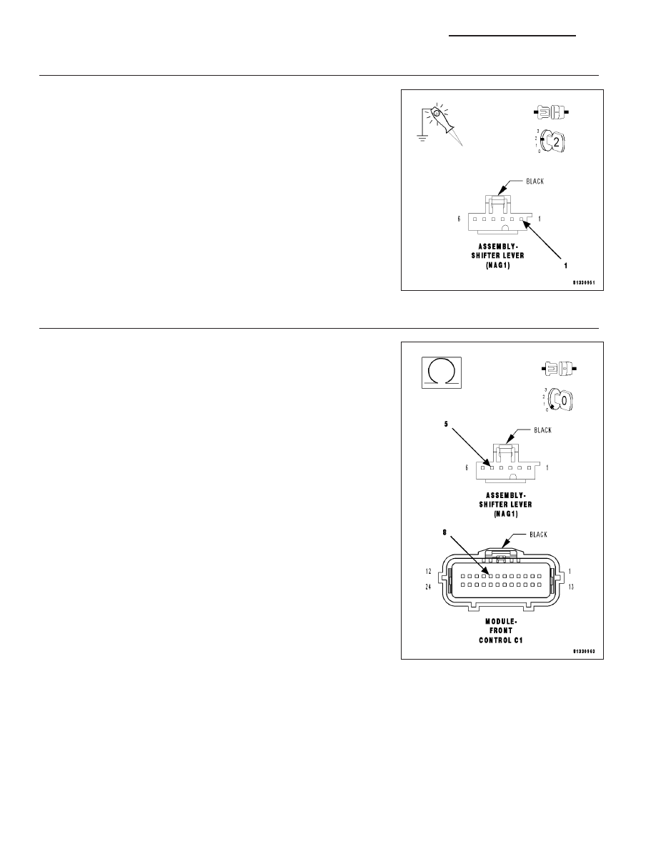
(F902) IGNITION UNLOCK–RUN–START CIRCUIT OPEN OR SHORTED

Turn the ignition on.

Using a 12-volt test light connected to ground, check the (F902) Ignition
Unlock–Run–Start circuit.

Does the test light illuminate brightly?

Yes

>> Go To 4

No

>> Repair the (F902) Ignition Unlock–Run–Start circuit for an

open or short.

Perform NAG1 TRANSMISSION VERIFICATION TEST -
VER 1.

4.

(D65) CAN C BUS (+) CIRCUIT OPEN

Turn the ignition off.

Disconnect the FCM C1 harness connector.

Measure the resistance of the (D65) CAN C Bus (+) circuit between the
FCM connector and the Shifter Lever Assembly connector.

Is resistance below 5.0 ohms?

Yes

>> Go To 5

No

>> Repair the (D65) CAN C Bus (+) circuit for an open.

Perform NAG1 TRANSMISSION VERIFICATION TEST -
VER 1.

8E - 166

ELECTRONIC CONTROL MODULES - ELECTRICAL DIAGNOSTICS

LX

5.

(D64) CAN C BUS (-) CIRCUIT OPEN

Measure the resistance of the (D64) CAN C Bus (-) circuit between the
FCM connector and the Shifter Lever Assembly connector.

Is resistance below 5.0 ohms?

Yes

>> Replace the Shifter Lever Assembly in accordance with the

service information.

Perform NAG1 TRANSMISSION VERIFICATION TEST -
VER 1.

No

>> Repair the (D64) CAN C Bus (-) circuit for an open.

Perform NAG1 TRANSMISSION VERIFICATION TEST -
VER 1.

LX

ELECTRONIC CONTROL MODULES - ELECTRICAL DIAGNOSTICS

8E - 167

*NO RESPONSE FROM ESM (ELECTRONIC SHIFT MODULE) - (COLUMN NAG1)

For a complete wiring diagram Refer to Section 8W.

8E - 168

ELECTRONIC CONTROL MODULES - ELECTRICAL DIAGNOSTICS

LX

Possible Causes

(Z910) GROUND CIRCUITS OPEN

(F902) IGNITION UNLOCK-RUN-START CIRCUIT OPEN OR SHORTED

(D65) CAN C BUS (+) CIRCUIT OPEN

(D64) CAN C BUS (-) CIRCUIT OPEN

ELECTRONIC SHIFT MODULE

Diagnostic Test

1.

TEST FOR INTERMITTENT CONDITION

Turn the ignition on.

NOTE: Ensure the IOD fuse is installed and battery voltage is between 10.0 and 16.0 volts.
With the scan tool, select ECU View.

NOTE: A red X will be next to the module that is not communicating, indicating that the module is not active
on the Bus network. A green check indicates that the module is active on the Bus network.

NOTE: Check the FCM for any active CAN C hardware and any ignition related DTCs, perform DTCs before
proceeding.

Does the scan tool display a red X next to the module?

Yes

>> Go To 2

No

>> The no response condition is not present at this time. Using the wiring diagram/schematic as a guide,

inspect the wiring for chafed, pierced, pinched, and partially broken wires and the wiring harness con-
nectors for broken, bent, pushed out, and corroded terminals.

2.

CHECK THE (Z910) GROUND CIRCUIT FOR AN OPEN

Turn the ignition off.

Disconnect the Electronic Shift Module harness connector.

Using a 12-volt test light connected to 12-volts, check the (Z910)
ground circuit.

Does the test light illuminate brightly?

Yes

>> Go To 3

No

>> Repair the (Z910) ground circuit for an open.

Perform NAG1 TRANSMISSION VERIFICATION TEST -
VER 1.

LX

ELECTRONIC CONTROL MODULES - ELECTRICAL DIAGNOSTICS

8E - 169


Content   ..  367  368  369  370   ..