Chrysler 300/300 Touring/300C, Dodge Magnum. Manual - part 367


  Index      Chrysler     Chrysler 300/300 Touring/300C, Dodge Magnum - service repair manual


Search            


Content   ..  365  366  367  368   ..


Chrysler 300/300 Touring/300C, Dodge Magnum. Manual - part 367


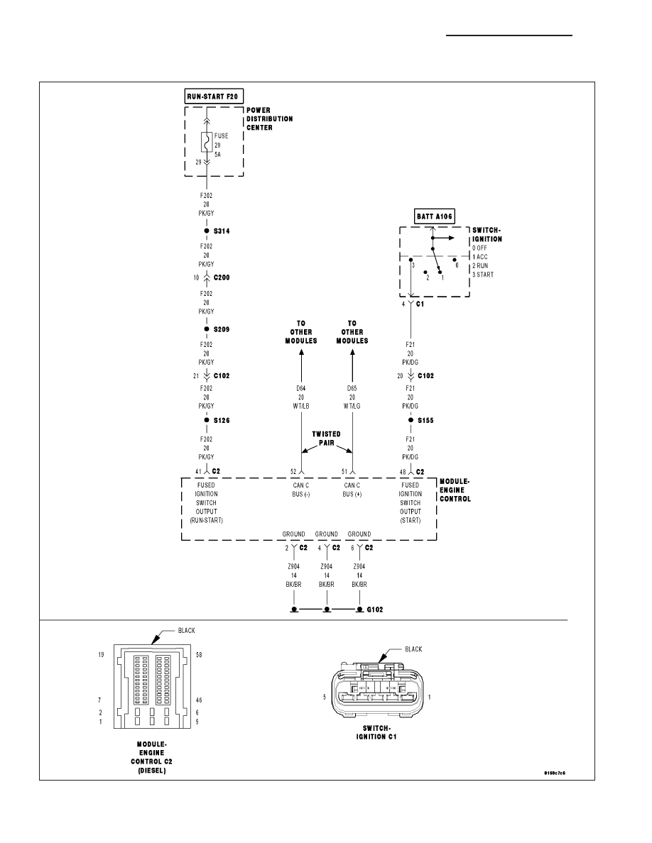
*NO RESPONSE FROM ECM (ENGINE CONTROL MODULE) - DIESEL

For a complete wiring diagram Refer to Section 8W.

8E - 158

ELECTRONIC CONTROL MODULES - ELECTRICAL DIAGNOSTICS

LX

Possible Causes

ENGINE CONTROL MODULE POWER AND GROUND

(D65) CAN C BUS (+) CIRCUIT OPEN

(D64) CAN C BUS (-) CIRCUIT OPEN

ENGINE CONTROL MODULE

Diagnostic Test

1.

TEST FOR INTERMITTENT CONDITION

Turn the ignition on.

NOTE: Ensure the IOD fuse is installed and battery voltage is between 10.0 and 16.0 volts.
With the scan tool, select ECU View.

NOTE: A red X will be next to the module that is not communicating, indicating that the module is not active
on the Bus network. A green check indicates that the module is active on the Bus network.

NOTE: Check the FCM for any active CAN C hardware and any ignition related DTCs, perform DTCs before
proceeding.

Does the scan tool display a red X next to the module?

Yes

>> Go To 2

No

>> The no response condition is not present at this time. Using the wiring diagram/schematic as a guide,

inspect the wiring for chafed, pierced, pinched, and partially broken wires and the wiring harness con-
nectors for broken, bent, pushed out, and corroded terminals.

2.

CHECK ECM POWER AND GROUND

Check the ECM power and ground circuits. Refer to 9 - ENGINE ELECTRICAL DIAGNOSTICS - DIESEL for the
diagnostic test procedure.

Were any problems found?

Yes

>> Repair as necessary.

Perform the ECM VERIFICATION TEST.

No

>> Go To 3

LX

ELECTRONIC CONTROL MODULES - ELECTRICAL DIAGNOSTICS

8E - 159

3.

(D65) CAN C BUS (+) CIRCUIT OPEN

Turn the ignition off.

Disconnect the FCM C1 harness connector.

Disconnect the ECM C2 harness connector.

Measure the resistance of the (D65) CAN C Bus (+) circuit between the
FCM connector and the ECM connector.

Is resistance below 5.0 ohms?

Yes

>> Go To 4

No

>> Repair the (D65) CAN C Bus (+) circuit for an open.

Perform the ECM VERIFICATION TEST.

4.

(D64) CAN C BUS (-) CIRCUIT OPEN

Measure the resistance of the (D64) CAN C Bus (-) circuit between the
FCM connector and the ECM connector.

Is resistance below 5.0 ohms?

Yes

>> Replace and program the Engine Control Module in accor-

dance with the service information.

Perform the ECM VERIFICATION TEST.

No

>> Repair the (D64) CAN C Bus (-) circuit for an open.

Perform the ECM VERIFICATION TEST.

8E - 160

ELECTRONIC CONTROL MODULES - ELECTRICAL DIAGNOSTICS

LX

*NO RESPONSE FROM EOM (ELECTRONIC OVERHEAD MODULE)

For a complete wiring diagram Refer to Section 8W.

LX

ELECTRONIC CONTROL MODULES - ELECTRICAL DIAGNOSTICS

8E - 161


Content   ..  365  366  367  368   ..