Chrysler 300/300 Touring/300C, Dodge Magnum. Manual - part 247


  Index      Chrysler     Chrysler 300/300 Touring/300C, Dodge Magnum - service repair manual


Search            


Content   ..  245  246  247  248   ..


Chrysler 300/300 Touring/300C, Dodge Magnum. Manual - part 247


INTEGRATED CONTROL UNIT - MK25E
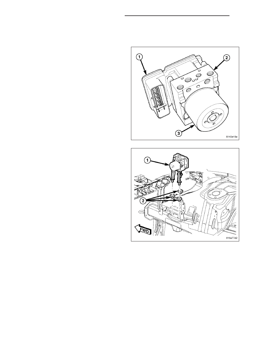
DESCRIPTION

NOTE: Later launch vehicles use the MK25E
Antilock Braking System (ABS). The MK25E ICU
can be easily identified by the brake tube ports on
two sides as shown instead of on one side as
used on previous systems.

The Hydraulic Control Unit (HCU) (2) and the Antilock
Brake Module (ABM) (1) used with this antilock brake
system are combined (integrated) into one unit, which
is called the Integrated Control Unit (ICU).

The ICU (1) is located in the engine compartment,
mounted to a bracket that is attached to the right side
rail through the use of isolation grommets (2).

The ABS with traction control ICU consists of the following components: the ABM, eight (build/decay) solenoid
valves (four inlet valves and four outlet valves), two traction control solenoid valves, two hydraulic shuttle valves,
valve block, fluid accumulators, a pump, and an electric pump/motor.

The replaceable components of the ICU are the HCU and the ABM. No attempt should be made to service any
components of the HCU or ABM.

For additional information on the ABM, (Refer to 8 - ELECTRICAL/ELECTRONIC CONTROL MODULES/ANTILOCK
BRAKE MODULE - DESCRIPTION).

5 - 430

BRAKES - ABS SERVICE INFORMATION

LX

REMOVAL

NOTE: Before proceeding, (Refer to 5 - BRAKES - WARNING) (Refer to 5 - BRAKES - CAUTION).

1. Disconnect and isolate battery negative cable (2)

from battery post.

2. Using a brake pedal holding tool, depress brake

pedal past its first inch of travel and hold it in this
position. Holding pedal in this position will isolate
master cylinder from hydraulic brake system and
will not allow brake fluid to drain out of brake fluid
reservoir while brake lines are open.

3. Remove primary (4) and secondary (1) brake tubes

(from master cylinder) at hydraulic control unit (7).

4. Remove remaining brake tubes (2, 3, 5, 6) at

hydraulic control unit (7).

LX

BRAKES - ABS SERVICE INFORMATION

5 - 431

NOTE: Use this figure in the following step to
release the ABM harness connector cover. It
shows the location of the release tabs.

5. Disconnect ABM harness connector from antilock

brake module (ABM). To do so:

a. Depress tabs on each side of connector cover,

then

b. Pull outward and upward on lower half of cover

until it locks into position pointing straight out-
ward (2). Connector can then be pulled straight
outward off ABM (1).

6. Pull up on unit (1) and remove from mounting

grommets (2) in body side rail.

5 - 432

BRAKES - ABS SERVICE INFORMATION

LX

DISASSEMBLY

1. Remove two screws attaching the mounting bracket to the HCU. Remove the bracket.

2. Remove four screws (1) attaching ABM (2) to HCU.

3. Separate ABM (1) from HCU (2).

ASSEMBLY

1. Clean any debris off the mating surfaces of the HCU and ABM.

CAUTION: When installing new O-rings or solenoid valve stem seals, do not use any type of lubricant.

LX

BRAKES - ABS SERVICE INFORMATION

5 - 433


Content   ..  245  246  247  248   ..