Chrysler 300/300 Touring/300C, Dodge Magnum. Manual - part 2342


  Index      Chrysler     Chrysler 300/300 Touring/300C, Dodge Magnum - service repair manual


Search            


Content   ..  2340  2341  2342  2343   ..


Chrysler 300/300 Touring/300C, Dodge Magnum. Manual - part 2342


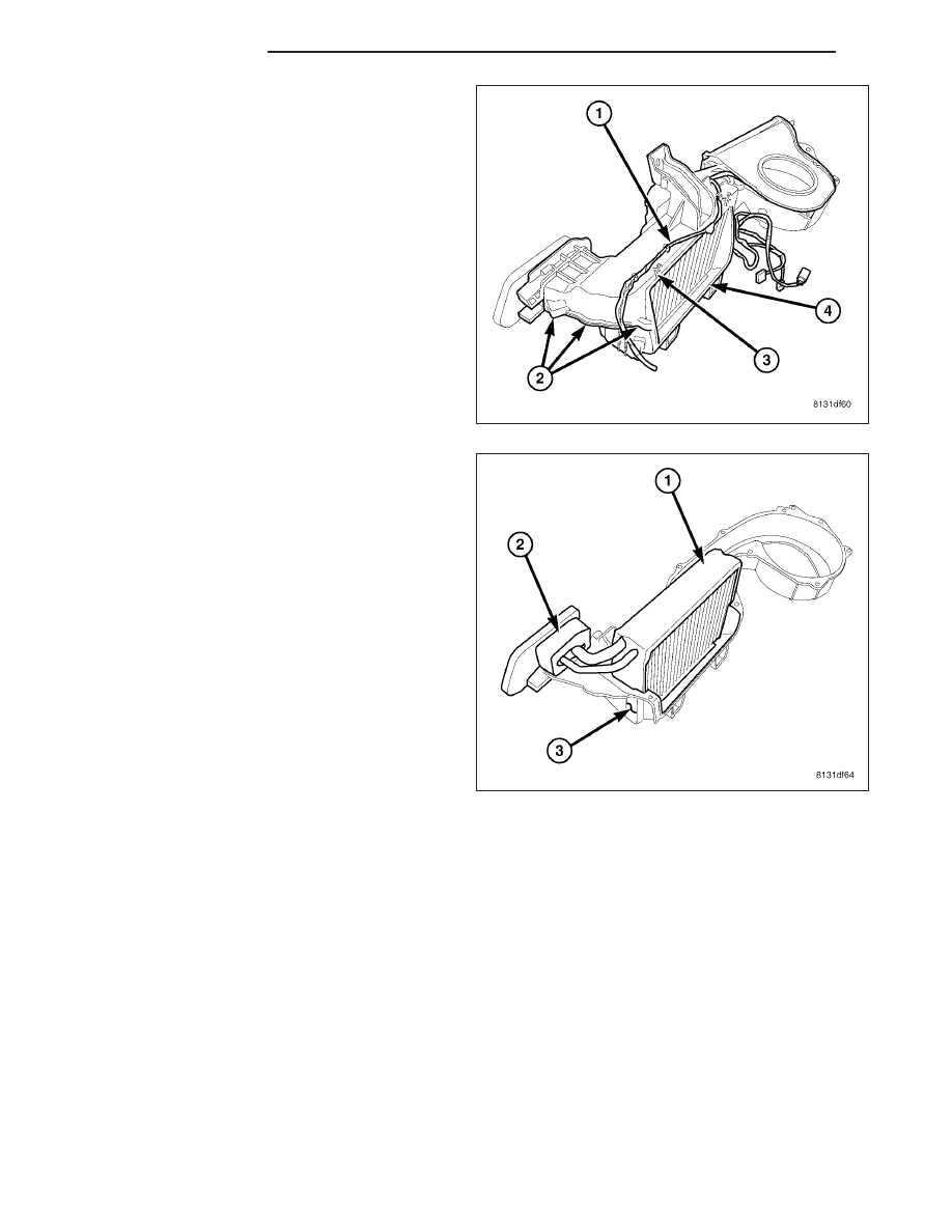
14. Remove the HVAC wiring harness (1).

15. Remove the ten screws (2) that secure the upper

half of the HVAC housing (3) to the lower half of
the HVAC housing (4).

16. Separate the two halves of the HVAC housing.

17. Carefully lift the A/C evaporator (1) and foam seal

(2) out of the lower half of the HVAC housing (3).

18. If required, remove the foam seal from the tapping

block of the A/C evaporator. If the seal is
deformed or damaged, it must be replaced.

ASSEMBLY

HOUSING-AIR DISTRIBUTION

NOTE: The air distribution housing must be removed from the HVAC housing and disassembled for service
of the mode-air and blend-air doors.

NOTE: LHD model shown in illustrations. RHD model similar.

24 - 402

DISTRIBUTION

LX

1. Install the air door(s) (1) into the air distribution

housing (2) as required. Align the air door with the
pivot shaft hole in the housing.

2. Align and install the air door lever (4) into the pivot

shaft of the air door. Make sure that the tab (3) on
the door lever is securely engaged to the pivot
shaft.

3. Align the air door pivot shafts with the pivot holes

in the center partition (3) and install the partition
onto the left half of the air distribution housing (1).

4. Align the air door pivot shafts to each other and

carefully install the left half of the air distribution
housing to the right half of the housing (2).

5. Install the screws (4) that secure the two halves of

the air distribution housing (3) together. Tighten the
screws to 2.2 N·m (20 in. lbs.).

6. Inspect the foam seal (1), especially at the parting

line (2). If the seal is deformed or damaged, it must
be replaced.

LX

DISTRIBUTION

24 - 403

7. Position the front floor distribution duct (2) onto the

air distribution housing (3).

8. Install the six screws (1) that secure the front floor

distribution duct to the air distribution housing.
Tighten the screws to 2 N·m (17 in. lbs.).

9. If equipped with dual zone heating-A/C, install the

blend door cam (1) onto the blend door lever (2)
and the pivot shaft located on the passenger side
of the air distribution housing (3).

10. If equipped with dual zone heating-A/C, position

the blend door actuator mounting bracket (5) onto
the passenger side of the air distribution housing
(3).

11. Install the screws (4) that secure the blend door

actuator mounting bracket to the air distribution
housing. Tighten the screws to 2 N·m (17 in. lbs.).

12. Position the blend door actuator (2) onto the air

distribution housing. If necessary, rotate the actua-
tor slightly to align the splines on the actuator out-
put shaft with those on the blend door cam (Refer
to 24 - HEATING & AIR CONDITIONING/CON-
TROLS/ACTUATOR-BLEND DOOR - INSTALLA-
TION).

13. Install the screws (1) that secure the blend door

actuator to the air distribution housing. Tighten the
screws to 2 N·m (17 in. lbs.).

24 - 404

DISTRIBUTION

LX

14. Carefully install the heater core (4) into the driver

side of the HVAC air distribution housing (3).

15. Install heater core retaining bracket (2) onto the

air distribution housing.

16. Install the screw (1) that secures the heater core

retaining bracket onto the air distribution housing.
Tighten the screw to 2.2 N·m (20 in. lbs.).

17. Install the blend door cam (9) onto the blend door

lever (10) and the pivot shaft located on the driver
side of the air distribution housing (8).

18. Install the floor door linkage (5) onto the floor door

lever (4) and the pivot shaft on air distribution
housing.

NOTE: Align the guide pin on the floor door link-
age with the guides on the mode door cam during
installation of the floor door linkage.

19. Install the mode door cam (6) onto the pivot shaft

on air distribution housing.

20. Connect the defrost/demister door linkage rod

(12) onto the defrost/demister door lever (11).

NOTE: Align the guide pin on the defrost/demister
linkage with the guides on the mode door cam
during installation of the defrost/demister linkage.

21. Install the defrost/demister linkage (7) onto the pivot shaft on air distribution housing.

22. Connect the instrument panel door linkage rod (2) onto the instrument panel door lever (1).

NOTE: Align the guide pin on the instrument panel linkage with the guides on the mode door cam during
installation of the instrument panel linkage.

23. Install the instrument panel linkage (3) onto the pivot shaft on air distribution housing.

LX

DISTRIBUTION

24 - 405


Content   ..  2340  2341  2342  2343   ..