Chrysler 300/300 Touring/300C, Dodge Magnum. Manual - part 2330


  Index      Chrysler     Chrysler 300/300 Touring/300C, Dodge Magnum - service repair manual


Search            


Content   ..  2328  2329  2330  2331   ..


Chrysler 300/300 Touring/300C, Dodge Magnum. Manual - part 2330


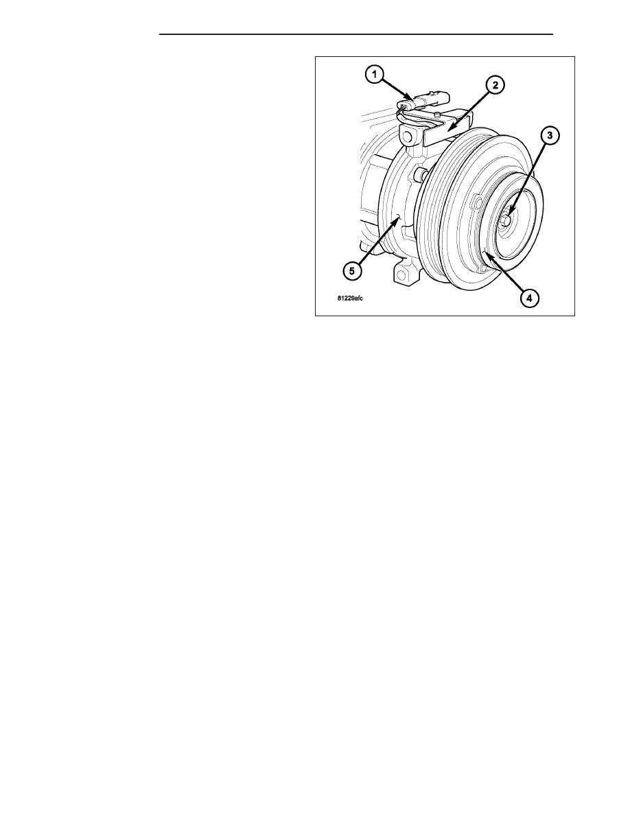
6. Install the clutch plate (4) onto the front of the A/C

compressor (5).

7. Install the compressor shaft bolt (3). Tighten the

bolt to 19 N·m (168 in. lbs.).

NOTE: The shims may compress after tightening
the shaft bolt. Check the air gap in four or more
places to verify the air gap is correct. Spin the pul-
ley before performing a final check of the air gap.

NOTE: On models with the clutch plate recessed
into the pulley, use a 90° wire gap gauge to mea-
sure the clutch air gap. On other models, use a
blade type feeler gauge to measure the air gap.

8. With the clutch plate assembled tight against the

shim(s), measure the air gap between the clutch
plate and the pulley and bearing assembly. The air
gap should be between 0.35 - 0.60 mm (0.014 -
0.024 in.). If the air gap is not between specifica-
tions, add or subtract shims as needed until the
correct air gap is obtained.

CAUTION: Be certain that the compressor clutch field coil wire lead is routed so that it is not pinched
between the A/C compressor and the field coil connector bracket.

9. Carefully route the compressor clutch field coil wire lead behind the connector bracket (2).

10. Install the compressor clutch field coil connector (1) onto the connector bracket.

11. If removed, position the A/C compressor to the engine and install the retaining bolts (Refer to 24 - HEATING &

AIR CONDITIONING/PLUMBING/COMPRESSOR-A/C - INSTALLATION).

12. Connect the engine wire harness to the compressor clutch field coil connector.

13. Install the accessory drive belt (Refer to 7 - COOLING/ACCESSORY DRIVE/BELTS-DRIVE - INSTALLATION).

14. Reconnect the negative battery cable.

24 - 354

CONTROLS

LX

CONTROL-A/C-HEATER

DESCRIPTION

MANUAL SINGLE ZONE

The A/C-heater control (1) for the manual temperature
control (MTC) single zone heating-A/C system allows
one temperature setting for the entire vehicle. All con-
trols are identified by ISO graphic symbols.

The A/C-heater control and integral computer is
located in the instrument panel and contains:

a rotary control knob for temperature control of
the discharged air (2).

a rotary control knob for recirculation and mode
control of the discharged air (3).

a push button rear window defogger on/off con-
trol (4). The defogger button contains an LED
that illuminates when the rear window defogger
system is in operation.

a push button A/C on/off control (5). The Snow-
flake button contains an LED that illuminates
when the A/C system is in operation.

a rotary control knob for fan speed selection and
turning the heating-A/C system off (6).

Prior to replacing an A/C-heater control, check for any diagnostic trouble codes (DTCs) related to the heating-A/C
system and run the calibration procedure to verify that the concern is not a system issue (Refer to 24 - HEATING
& AIR CONDITIONING - DIAGNOSIS AND TESTING - HEATING AND A/C SYSTEMS) and to 24 - HVAC Electrical
Diagnostics for more information.

The A/C-heater control cannot be repaired and, if faulty or damaged, it must be replaced.

AUTOMATIC DUAL ZONE

The A/C-heater control (1) for the automatic temperature control (ATC) dual zone heating-A/C system allows both
the driver and the front seat passenger the ability to individually regulate air temperature for their side of the vehicle.
All controls are identified by ISO graphic symbols.

The ATC A/C-heater control and integral computer is
located in the instrument panel and contains:

a push button A/C on/off control (2). The Snow-
flake button contains an LED that illuminates
when the A/C system is in operation.

a push button rear window defogger on/off con-
trol (3). The defogger button contains an LED
that illuminates when the rear window defogger
system is in operation.

an infrared sensor (4) that detects thermal radia-
tion emitted by the front seat occupants and their
surroundings

a push button air recirculation control (5). The
Recirculation button contains an LED that illumi-
nates when the recirculation function is manually
activated.

a rotary control knob for mode control of the dis-
charged air (6).

two rotary control knobs for individual driver and
front seat passenger temperature control of the discharged air (7).

LX

CONTROLS

24 - 355

a rotary control knob for manual and automatic fan speed selection and turning the heating-A/C system off (8).

Auto mode provides variable air recirculation under high temperature and humidity conditions. Because recir-
culation is generally accompanied by increased fan noise, the proportion of recirculated to outside air gradually
approaches full recirculation over a broad temperature range.

The A/C-heater control for the ATC dual zone heating-A/C system is diagnosed using a scan tool. Prior to replacing
an A/C-heater control, run the calibration procedure to verify that the concern is not a system issue. )Refer to 24 -
HEATING & AIR CONDITIONING - DIAGNOSIS AND TESTING - HEATING AND A/C SYSTEMS) and to 24 - HVAC
Electrical Diagnostics for more information.

NOTE: ATC A/C-heater controls are NOT interchangeable between other model years or other vehicle lines.
If replacement of the A/C-heater control is required, only use the control designed for the vehicle being
serviced.

The A/C-heater control cannot be repaired and, if faulty or damaged, it must be replaced.

The A/C-heater control utilizes integrated circuitry and information carried on the controller area network (CAN) B
bus to monitor many sensors and switch inputs throughout the vehicle. In response to those inputs, the internal
circuitry and programming of the A/C-heater control allows it to control electronic functions and features of the ATC
heating-A/C system.

Some of the inputs received by the A/C-heater control of the ATC heating-A/C system on the CAN B bus are as
follows:

Dimming

Refrigerant Pressure

A/C Clutch Engage

Vehicle Identification Number

Vehicle Odometer

Engine Coolant Temperature

Ambient Air Temperature

System Voltage

Vehicle Speed

Engine Speed

Some of the messages broadcasted by the A/C-heater control of the ATC heating-A/C system on the CAN B bus
are as follows:

A/C Request

A/C Select

EBL Status

Auto Headlamp Signal

REMOVAL

WARNING: On vehicles equipped with airbags, disable the airbag system before attempting any steering
wheel, steering column, or instrument panel component diagnosis or service. Disconnect and isolate the
negative battery (ground) cable, then wait two minutes for the airbag system capacitor to discharge before
performing further diagnosis or service. This is the only sure way to disable the airbag system. Failure to
take the proper precautions could result in accidental airbag deployment and possible personal injury or
death.

NOTE: ATC A/C-heater controls are NOT interchangeable between other model years or other vehicle lines.
If replacement of the A/C-heater control is required, only use the control designed for the vehicle being
serviced.

24 - 356

CONTROLS

LX

1. Disconnect and isolate the negative battery cable.

2. Remove the center bezel (1) from the instrument

panel (2), disconnect the wire harness connector(s)
(3) from the A/C-heater control (4) and place the
center bezel on a workbench (Refer to 23 - BODY/
INSTRUMENT PANEL/INSTRUMENT PANEL CEN-
TER BEZEL - REMOVAL).

3. Remove the four screws (1) that secure the A/C-

heater control (2) to the instrument panel center
bezel (3).

4. Remove the A/C-heater control from the instrument

panel center bezel.

LX

CONTROLS

24 - 357


Content   ..  2328  2329  2330  2331   ..