Chrysler 300/300 Touring/300C, Dodge Magnum. Manual - part 2276


  Index      Chrysler     Chrysler 300/300 Touring/300C, Dodge Magnum - service repair manual


Search            


Content   ..  2274  2275  2276  2277   ..


Chrysler 300/300 Touring/300C, Dodge Magnum. Manual - part 2276


3.

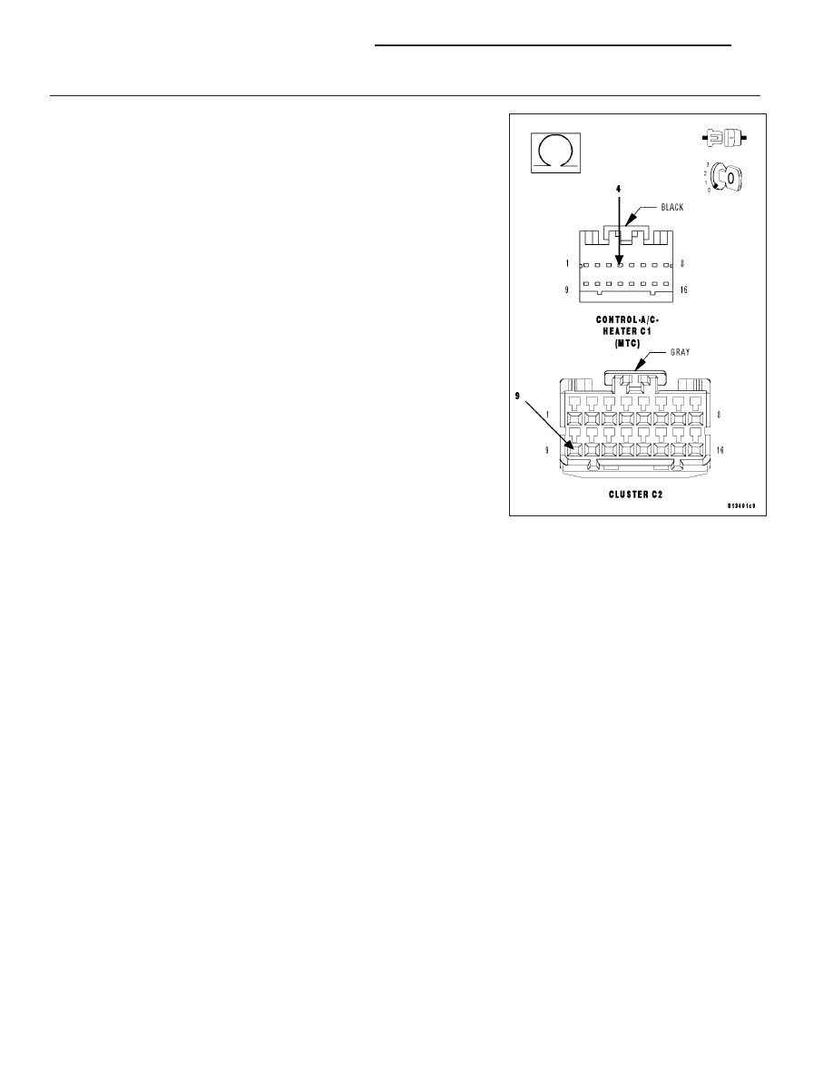
CHECK (C105) HVAC MUX CONTROL CIRCUIT FOR AN OPEN

Measure the resistance of the (C105) HVAC MUX Control circuit
between the A/C Heater Control C1 harness connector and the Instru-
ment Cluster C2 harness connector.

Is the resistance below 5.0 ohms?

Yes

>> Replace the Instrument Cluster (CCN) in accordance with

the Service Information.

Perform BODY VERIFICATION TEST – VER 1. (Refer to 8
-

ELECTRICAL/ELECTRONIC

CONTROL

MODULES/

FRONT CONTROL MODULE - DIAGNOSIS AND TEST-
ING).

No

>> Repair the (C105) HVAC MUX Control circuit for an open.

Perform BODY VERIFICATION TEST – VER 1. (Refer to 8
-

ELECTRICAL/ELECTRONIC

CONTROL

MODULES/

FRONT CONTROL MODULE - DIAGNOSIS AND TEST-
ING).

75–AC REQUEST OUTPUT SIGNAL HIGH WHEN DRIVEN LOW (MTC)

For a complete wiring diagram Refer to Section 8W.

When Monitored:
With the ignition on.

Set Condition:
If the A/C Heater Control detects voltage above 4.49 volts on the (C105) HVAC MUX Control circuit with the
A/C switched on.

NOTE: This DTC must be active for the results of this test to be valid. Do not perform this test if this DTC
is stored. Refer to HVAC System Test (MTC) for stored DTC test procedures.

Refer to 73–AC REQUEST OUTPUT SIGNAL TOO HIGH for the diagnostic test procedure.

76–AC REQUEST OUTPUT SIGNAL LOW WHEN DRIVEN HIGH (MTC)

For a complete wiring diagram Refer to Section 8W.

When Monitored:
With the ignition on.

Set Condition:
If the A/C Heater Control detects voltage below 1.51 volts on the (C105) HVAC MUX Control circuit when the
A/C is switched off.

NOTE: This DTC must be active for the results of this test to be valid. Do not perform this test if this DTC
is stored. Refer to HVAC System Test (MTC) for stored DTC test procedures.

Refer to 74–AC REQUEST OUTPUT SIGNAL TOO LOW for the diagnostic test procedure.

24 - 138

HVAC - ELECTRICAL DIAGNOSTICS

LX

77–EBL OUTPUT SHORTED HIGH

For a complete wiring diagram Refer to Section 8W.

LX

HVAC - ELECTRICAL DIAGNOSTICS

24 - 139

When Monitored:
With the ignition on and the EBL mode switch on.

Set Condition:
If the A/C Heater Control senses excessive current on the (C115) Defogger Relay Control circuit.

Possible Causes

(C115) DEFOGGER RELAY CONTROL CIRCUIT SHORTED TO BATTERY

EBL RELAY SHORTED

A/C HEATER CONTROL

NOTE: This DTC must be active for the results of this test to be valid. Do not perform this test if this DTC
is stored. Refer to HVAC System Test (MTC) for stored DTC test procedures.

Diagnostic Test

1.

CHECK FOR A SHORTED EBL RELAY

Turn the ignition off.

Install a known good relay in place of the EBL relay.

Turn the ignition on.

Actuate the Clear DTC function by performing the following:

Turn the blower control on.

Press the A/C mode switch down, turn the blower control to off,
wait until both LEDs illuminate (approximately 5 seconds) and then
release the A/C mode switch.

When the A/C status indicator begins displaying DTCs, set the
Mode switch to the floor position, simultaneously press the A/C
mode switch and the EBL mode switch down until both LEDs start
flashing (approximately 5 seconds) and then release the mode
switches. Stored DTCs will clear from memory in approximately
two seconds.

Press the EBL mode switch on.

Actuate the Display DTC function by performing the following:

Turn the blower control on.

Press the A/C mode switch down, turn the blower control to off, wait until both LEDs illuminate (approximately
5 seconds) and then release the A/C mode switch.

NOTE: The A/C status indicator displays active DTCs when the EBL status indictor is not illuminated and
stored DTCs when the EBL status indicator is illuminated.
Read DTCs from the A/C status indictor.

Does the A/C status indicator display DTC 77?

Yes

>> Go To 2

No

>> Replace the original EBL Relay in accordance with the Service Information.

Perform BODY VERIFICATION TEST – VER 1. (Refer to 8 - ELECTRICAL/ELECTRONIC CONTROL
MODULES/FRONT CONTROL MODULE - DIAGNOSIS AND TESTING).

24 - 140

HVAC - ELECTRICAL DIAGNOSTICS

LX

2.

CHECK THE (C115) DEFOGGER RELAY CONTROL CIRCUIT FOR A SHORT TO BATTERY

Turn the ignition off.

Remove the replacement EBL relay.

Disconnect the A/C Heater Control C1 harness connector.

Turn the ignition on.

Measure the voltage of the (C115) Defogger Relay Control circuit.

Is the voltage above 0.2 volts?

Yes

>> Repair the (C115) Defogger Relay Control circuit for a short

to battery. Reinstall the original EBL relay.

Perform BODY VERIFICATION TEST – VER 1. (Refer to 8
-

ELECTRICAL/ELECTRONIC

CONTROL

MODULES/

FRONT CONTROL MODULE - DIAGNOSIS AND TEST-
ING).

No

>> Replace the A/C Heater Control in accordance with the Ser-

vice Information. Reinstall the original EBL relay.

Perform BODY VERIFICATION TEST – VER 1. (Refer to 8
-

ELECTRICAL/ELECTRONIC

CONTROL

MODULES/

FRONT CONTROL MODULE - DIAGNOSIS AND TEST-
ING).

LX

HVAC - ELECTRICAL DIAGNOSTICS

24 - 141


Content   ..  2274  2275  2276  2277   ..