Content .. 2164 2165 2166 2167 ..
Chrysler 300/300 Touring/300C, Dodge Magnum. Manual - part 2166
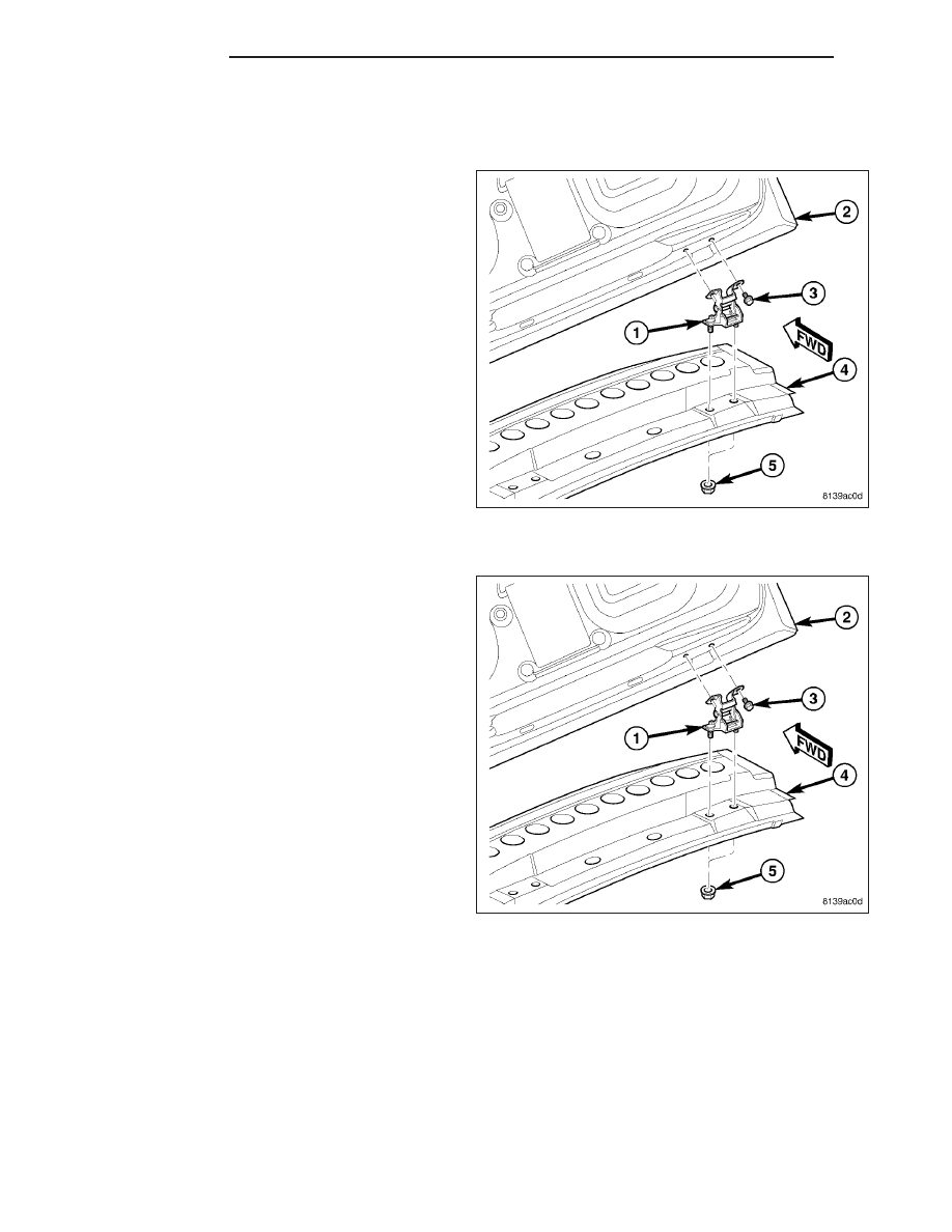
HINGE
REMOVAL
1. Open and support the liftgate (2) with a suitable
prop or block.
2. Remove the trim plate from the upper liftgate open-
ing header (4). (Refer to 23 - BODY/INTERIOR/
LIFTGATE OPENING UPPER TRIM - REMOVAL).
3. Mark the hinge (1) liftgate half location on the lift-
gate inner panel to aid reinstallation.
4. Remove the two screws (3) that secure the hinge
to the liftgate.
5. Mark the hinge body half location on the upper lift-
gate opening header to aid reinstallation.
6. Carefully pull the rear edge of the headliner down-
ward from the header far enough to access and
remove the two nuts (5) that secure the hinge
studs to the underside of the header.
7. Remove the hinge from the vehicle.
INSTALLATION
1. Position the body half of the liftgate hinge (1) to the
upper liftgate opening header (4) on the vehicle.
2. Carefully pull the rear edge of the headliner down-
ward from the header far enough to install and
tighten the two nuts (5) that secure the hinge studs
to the underside of the header. Tighten the nuts to
28 N·m (21 ft. lbs.).
3. Position the liftgate (2) to the liftgate half of the
hinge on the vehicle.
4. Install and tighten the two screws (3) that secure
the hinge to the liftgate. Tighten the screws to 28
N·m (21 ft. lbs.).
5. Remove the fixture being used to support the lift-
gate for service.
6. Adjust the liftgate hinge position as necessary to
achieve proper spacing and operation.
7. Reinstall the trim plate onto the upper liftgate open-
ing header. (Refer to 23 - BODY/INTERIOR/LIFT-
GATE OPENING UPPER TRIM - INSTALLATION).
23 - 212
LIFTGATE
LX