Chrysler 300/300 Touring/300C, Dodge Magnum. Manual - part 2165


  Index      Chrysler     Chrysler 300/300 Touring/300C, Dodge Magnum - service repair manual


Search            


Content   ..  2163  2164  2165  2166   ..


Chrysler 300/300 Touring/300C, Dodge Magnum. Manual - part 2165


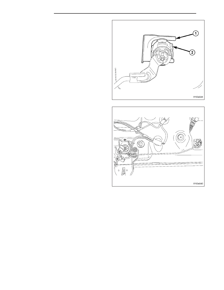
3. Fasten lock cylinder (2) to liftgate using lock cylin-

der clip (1).

4. Connect remote handle link to lock cylinder.

5. Reinstall lower liftgate trim panel. (Refer to 23 - BODY/DECKLID/HATCH/LIFTGATE/TAILGATE/TRIM PANEL -

INSTALLATION)

23 - 208

LIFTGATE

LX

BUMPER

REMOVAL

1. Open the liftgate.

2. Remove the two screws (3) that secure the stabi-

lizer bumper (2) to the liftgate opening drain trough
(1).

3. Remove the bumper from the trough.

INSTALLATION

1. Position the stabilizer bumper (2) to the two mount-

ing holes on the liftgate opening drain trough (1)
with the arrow molded into the bumper pointed
inboard.

2. Install and tighten the two screws (3) that secure

the bumper to the trough. Tighten the screws to 12
N·m (9 ft. lbs.).

3. Close the liftgate.

LX

LIFTGATE

23 - 209

GAS PROP

REMOVAL

1. Open and support the liftgate with a suitable prop

or block.

WARNING: To avoid personal injury or death, dur-
ing service lift the ball socket end retaining clip
only far enough to release the socket from the ball
stud. Excessive prying or removal of the clip may
result in improper clip spring tension. Improper
clip tension may result in the support cylinder
separating from the ball stud causing sudden,
unexpected loss of deck lid support.

2. Insert a small flat-bladed tool (3) into the notch on

the outer face of one ball socket end (1) of the
support cylinder and carefully pry the retaining clip
(2) outward while pulling the ball socket away from
the ball stud (4) on the liftgate or the liftgate open-
ing trough.

3. Release the retaining clip to its installed position.

4. Repeat Step 2 and Step 3 for the opposite end of

the support cylinder.

5. Remove the support cylinder from the liftgate and liftgate opening.

INSTALLATION

1. Check to be certain that the ball studs (2) on the

liftgate and on the liftgate opening trough (3) are in
good condition and properly installed. Tighten the
ball studs to 28 N·m (21 ft. lbs.).

2. Position the ball socket on the cylinder end of the

support cylinder (1) to the ball stud on the liftgate
opening trough.

3. Using hand pressure, press the ball socket onto

the ball stud until the retainer clip snaps into place.

23 - 210

LIFTGATE

LX

4. Position the ball socket on the rod end of the sup-

port cylinder (3) to the ball stud (2) on the liftgate
(1).

5. Using hand pressure, press the ball socket onto

the ball stud until the retainer clip snaps into place.

6. Inspect to be certain that the retaining clip on each

of the support cylinder ball socket ends is fully
seated.

7. Remove the service prop or block and close the

liftgate.

LX

LIFTGATE

23 - 211


Content   ..  2163  2164  2165  2166   ..