Content .. 2144 2145 2146 2147 ..
Chrysler 300/300 Touring/300C, Dodge Magnum. Manual - part 2146
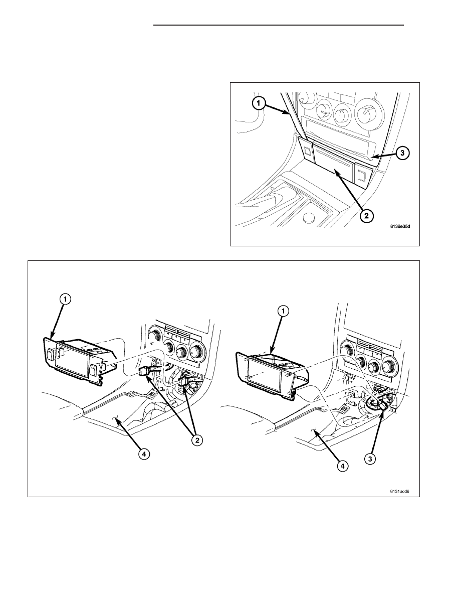
ASH RECEIVER
REMOVAL
1. Disconnect and isolate the negative battery cable.
2. Remove the gear shift center bezel from the floor
console (4) (Refer to 23 - BODY/INTERIOR/CON-
SOLE-FLOOR - REMOVAL).
3. Set the emergency brake and place the gear shift
lever into Low gear.
4. Using a trim stick C-4755 or equivalent (1), remove
the ash receiver (2) from the instrument panel (3)
by releasing the snap retainers from the instrument
panel.
5. If equipped, disconnect the wire harness connectors (2) from the heated seat switches and remove the switches
as required (Refer to 8 - ELECTRICAL/HEATED SEATS/SWITCH-HEATED SEAT - REMOVAL).
6. Disconnect the wire harness connector (3) from the lighter and remove the lighter assembly as required.
7. Remove the ash receiver from the vehicle.
23 - 132
INSTRUMENT PANEL
LX