Content .. 2140 2141 2142 2143 ..
Chrysler 300/300 Touring/300C, Dodge Magnum. Manual - part 2142
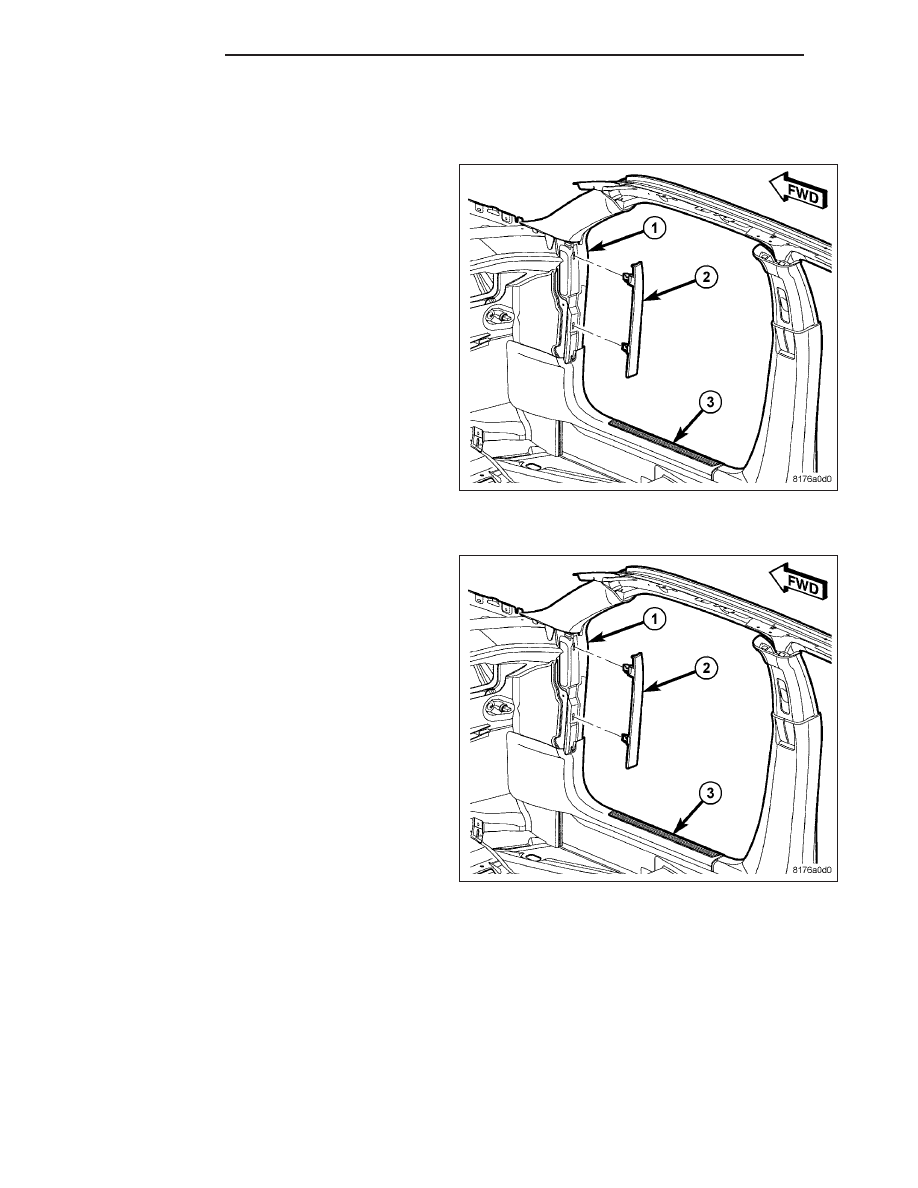
COWL EXTENSION TRIM
REMOVAL
1. Insert special tool C-4755 (from the outside in the
direction of arrow 2) under the middle of the trim
extension (2).
2. Slide trim stick up to the upper spring clip retainer,
and pry to disengage clip.
3. Slide the trim stick down to the lower spring clip
retainer, and pry to disengage clip.
INSTALLATION
1. Place trim extension (2) against cowl (1) and align
spring clips with holes on cowl.
2. Tap trim extension on to cowl (1) ensuring trim
extension (2) is properly seated.
23 - 116
EXTERIOR
LX