Content .. 2126 2127 2128 2129 ..
Chrysler 300/300 Touring/300C, Dodge Magnum. Manual - part 2128
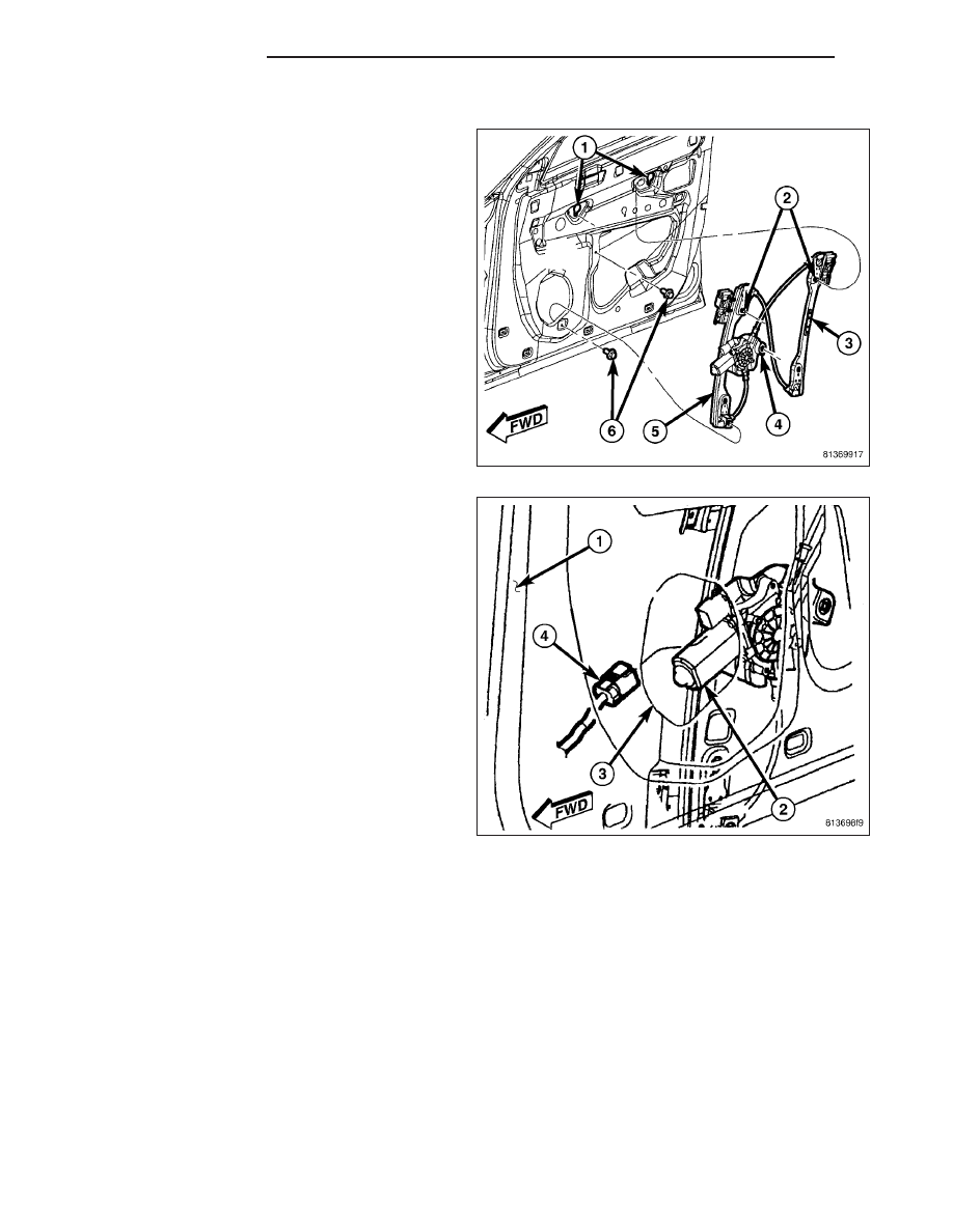
INSTALLATION
1. Load the regulator into the door through the large
access hole on the inside of the door near the rear.
2. Engage the screw (2) at the top of the rear regula-
tor rail (3) into the keyed hole (1) on the inside of
the door near the rear.
3. Position the front regulator rail within the door (1)
so that the door wire harness connector (4) can be
reconnected to the regulator motor (2) through the
speaker mounting hole (3) on the inside of the door
near the front.
4. Engage the screw at the top of the front regulator
rail into the keyed hole on the inside of the door
near the front.
5. Install and tighten the two screws that secure the
bottom of the front regulator rail and the regulator
motor support bracket to the inside of the door.
Tighten the screws to 10 N·m (90 in. lbs.).
6. Tighten the two screws that secure the tops of both
regulator rails to the keyed holes on the inside of
the door. Tighten the screws to 10 N·m (90 in. lbs.).
23 - 60
DOOR - FRONT
LX