Content .. 2022 2023 2024 2025 ..
Chrysler 300/300 Touring/300C, Dodge Magnum. Manual - part 2024
3.
PCM AND WIRING
Turn the ignition off to the lock position.
Remove the Starter Relay.
CAUTION: Removal of the Starter Relay is to prevent a Transmission, NO RESPONSE, condition and disable
the starter.
Install the Transmission Simulator, Miller tool #8333 and the Electronic Transmission Adapter kit 8333-1A.
Ignition on, engine not running.
With the Transmission Simulator, turn the Pressure Switch selector switch to LR.
With the scan tool, monitor the LR Pressure Switch State while pressing the Pressure Switch Test button.
Did the Pressure Switch state change from open to closed when the test button was pressed?
Yes
>> Go To 4
No
>> Go To 5
4.
INTERNAL TRANSMISSION
If there are no possible causes remaining, view repair.
Repair
Repair internal transmission as necessary per the Service Information. Inspect the Solenoid Switch
Valve per the Service Information and repair or replace as necessary. If no problems are found, replace
the Transmission Solenoid/Pressure Switch Assembly.
Perform 42RLE TRANSMISSION VERIFICATION TEST - VER 1. (Refer to 21 - TRANSMISSION/
TRANSAXLE/AUTOMATIC - 42RLE - STANDARD PROCEDURE)
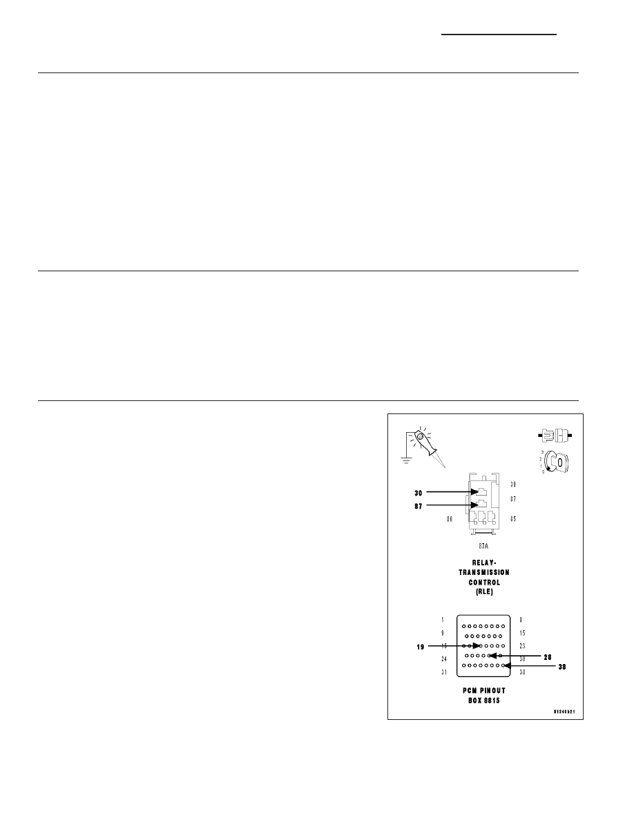
5.
(T16) TRANSMISSION CONTROL RELAY OUTPUT CIRCUIT OPEN
Turn the ignition off to the lock position.
Disconnect the Transmission Solenoid/Pressure Switch Assembly har-
ness connector.
Remove the Transmission Control Relay.
Connect a jumper wire between the (A104) Fused B+ circuit and the
(T16) Transmission Control Relay Output circuit.
NOTE: Check connectors - Clean/repair as necessary.
CAUTION: Do not probe the PCM harness connectors. Probing the
PCM harness connectors will damage the PCM terminals resulting
in poor terminal to pin connection. Install Miller Special Tool #8815
to perform diagnosis.
Disconnect the PCM C4 harness connector.
Remove the Starter Relay.
Using a 12-volt test light connected to ground, check all (T16) Trans-
mission Control Relay Output circuits in the appropriate terminals of
special tool #8815.
NOTE: The test light must illuminate brightly. Compare the bright-
ness to that of a direct connection to the battery.
Does the test light illuminate brightly on all Transmission Con-
trol Relay Output circuits?
Yes
>> Go To 6
No
>> Repair the (T16) Transmission Control Relay Output circuit
for an open.
Perform 42RLE TRANSMISSION VERIFICATION TEST - VER 1. (Refer to 21 - TRANSMISSION/
TRANSAXLE/AUTOMATIC - 42RLE - STANDARD PROCEDURE)
21 - 630
AUTOMATIC TRANSMISSION 42RLE - ELECTRICAL DIAGNOSTICS
LX