Chrysler 300/300 Touring/300C, Dodge Magnum. Manual - part 1838


  Index      Chrysler     Chrysler 300/300 Touring/300C, Dodge Magnum - service repair manual


Search            


Content   ..  1836  1837  1838  1839   ..


Chrysler 300/300 Touring/300C, Dodge Magnum. Manual - part 1838


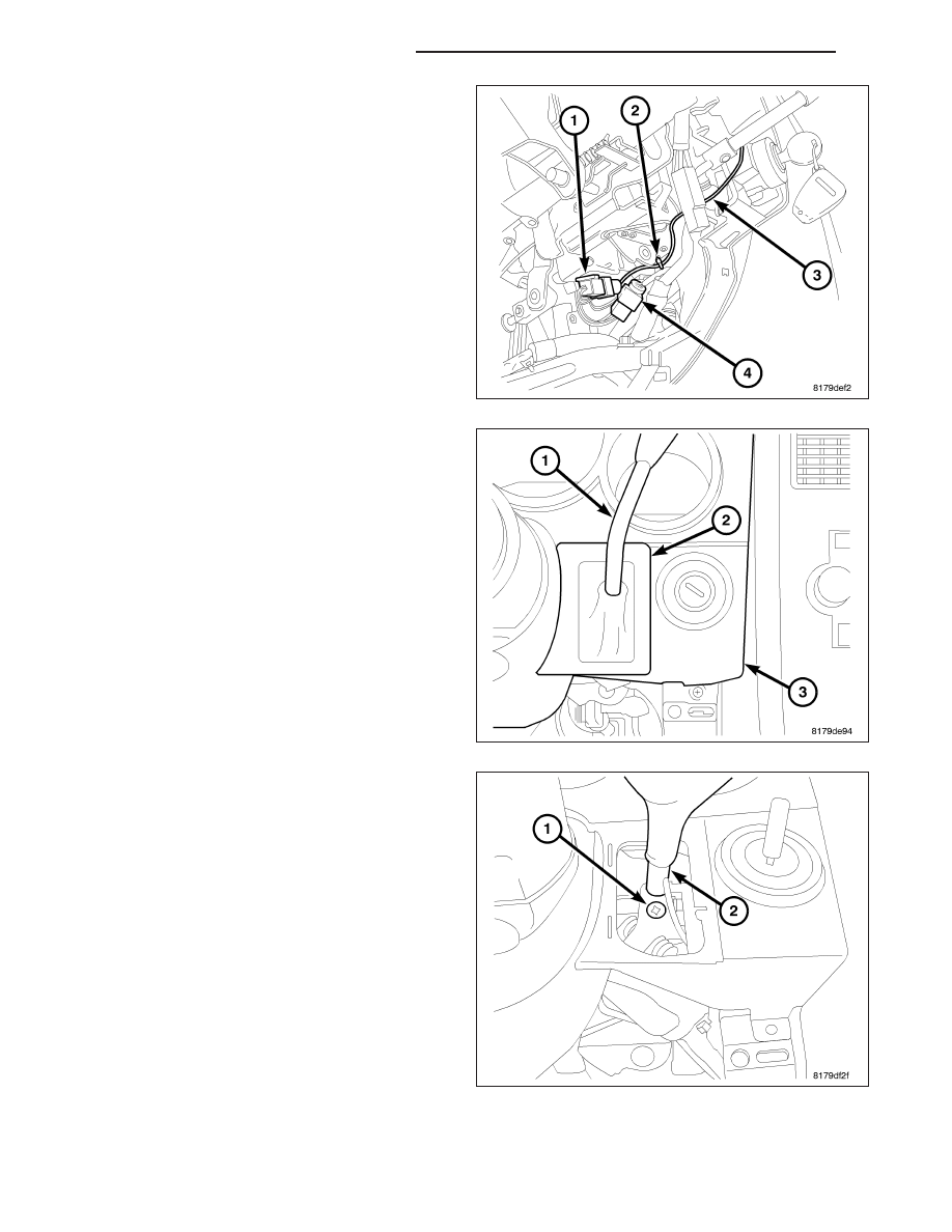
4. Disconnect the autostick wiring connector (1).

5. Remove the wiring tie strap (2) securing the auto-

stick wiring to the column.

6. Unsnap the gear shift lever boot (2) from the clus-

ter bezel (3). Slide the boot up the gear shift lever
(1), away from the bezel.

7. Remove the gear shift lever mounting screw (1).

8. Slide the gear shift lever (2) out of the column shift

mechanism and remove the lever with autostick
wiring.

19 - 170

COLUMN SERVICE INFORMATION

LX

INSTALLATION

1. Feed the autostick wiring through the hole in the

cluster bezel and slide the gear shift lever (2) into
the column shift mechanism.

2. Line up the threaded hole in the lever with the hole

in the shift mechanism and install the gear shift
lever mounting screw (1). Tighten the screw to 12
N·m (106 in. lbs.).

3. Slide the gear shift lever boot down gear shift lever

(1) and snap it into place on the cluster bezel (3).

4. Route the autostick wiring (3) along the right side

of the column gear shift mechanism and install a
wiring tie strap (2) securing the autostick wiring to
the column.

5. Connect the autostick wiring connector (1).

6. Check autostick wiring (3), making sure it is routed

away from movable portions of shift mechanism.

LX

COLUMN SERVICE INFORMATION

19 - 171

7. Install the steering column opening reinforcement

(1).

8. Install the steering column opening cover (1).

9. Install the negative battery terminal on the battery. It is important that this is performed properly (including cali-

bration of steering angle sensor if equipped with ESP). (Refer to 8 - ELECTRICAL/BATTERY SYSTEM - STAN-
DARD PROCEDURE)

CAUTION: If the steering wheel is excessively off-center while driving, outside of Chassis specifications,
inadvertent ESP activations may occur on a vehicle so equipped.

10. Test the operation of the gear shift lever and autostick functions.

19 - 172

COLUMN SERVICE INFORMATION

LX

MODULE-STEERING COLUMN CONTROL

DESCRIPTION

Tilt and telescope steering columns are standard on all models. On 300 Hemi C and international 300C models the
tilt and telescope functions are powered and are also included in the standard Memory System settings. Combined
with available power seats and optional power adjustable pedals, the tilt and telescope steering column gives the
driver every known adjustment to obtain a comfortable driving position. Both columns provide 2.36 inches (60 mm)
of telescoping adjustment and 5.2 degrees of tilt. The adjustments are continuously variable for maximum adapt-
ability.

A lever on the left side of the column controls powered adjustment. Fore and aft motion of the lever operates the
telescoping mechanism. Up and down motion operates the tilt mechanism. Two electric motors turning threaded
actuators move the column. The mechanisms lock in place when movement stops.

The Steering Column Control Module (SCCM) is mounted on the steering column and is removed as a complete
unit. The components that are contained within this unit are:

Clockspring - is attached to the top of the SCCM with three screws. The clockspring connector passes
through the body of the SCCM and its terminals slide into the male side of the self docking connector within
the Steering Column Module (SCM). (Refer to 8 - ELECTRICAL/RESTRAINTS - DESCRIPTION).

Multi-Function Switch - is the middle left lever, and is plugged into, and mounting pins pass through, the
SCM secured to the SCCM housing by three screws (Refer to 8 - ELECTRICAL/LAMPS/LIGHTING - EXTE-
RIOR/MULTI-FUNCTION SWITCH - DESCRIPTION).

Speed Control Switch - is the top left lever and is plugged into the SCM and held in place by the three
screws of the clockspring (Refer to 8 - ELECTRICAL/SPEED CONTROL - DESCRIPTION).

Steering Angle Sensor (if equipped with Electronic Stability Program (ESP) - is mounted on the right side
of the SCCM, below the clockspring and is responsible for informing the ESP of steering angle.

Steering Control Module (SCM) - is the module located in the bottom of the SCCM, retained by three screws,
and is the mating point for all the switches and clockspring located in the SCCM.

Tilt/Telescopic Lever/Switch (if equipped) - is the bottom left lever and is used for steering wheel tilt and
telescoping. It is plugged into the SCM and if not equipped, will be replaced by a support bar. It is held in
place by one the three clockspring screws and one of its own retaining screws.

Shroud - is the outer housing or shell of the SCCM.

The SCCM communicates via the Local Interconnect Network (LIN) serial data bus. This is an ultra-low voltage
serial data bus that allows the following components to communicate with the Controller Area Network (CAN) B and
C data buses.

Steering Wheel Switches

Horn

Speed Control Switch

Multi-function Switch

Tilt/Telescoping Switch (if equipped)

Steering Angle Sensor (if equipped with Electronic Stability Program (ESP)

Steering Column Module (SCM)

REMOVAL

WARNING: Before servicing the steering column the airbag system must be disarmed. Refer to electrical
restraint system for service procedures. Failure to do so may result in accidental deployment of the airbag
and possible personal injury or death.

CAUTION: All fasteners must be torqued to specification to ensure proper operation of the steering column.

LX

COLUMN SERVICE INFORMATION

19 - 173


Content   ..  1836  1837  1838  1839   ..