Chrysler 300/300 Touring/300C, Dodge Magnum. Manual - part 1755


  Index      Chrysler     Chrysler 300/300 Touring/300C, Dodge Magnum - service repair manual


Search            


Content   ..  1753  1754  1755  1756   ..


Chrysler 300/300 Touring/300C, Dodge Magnum. Manual - part 1755


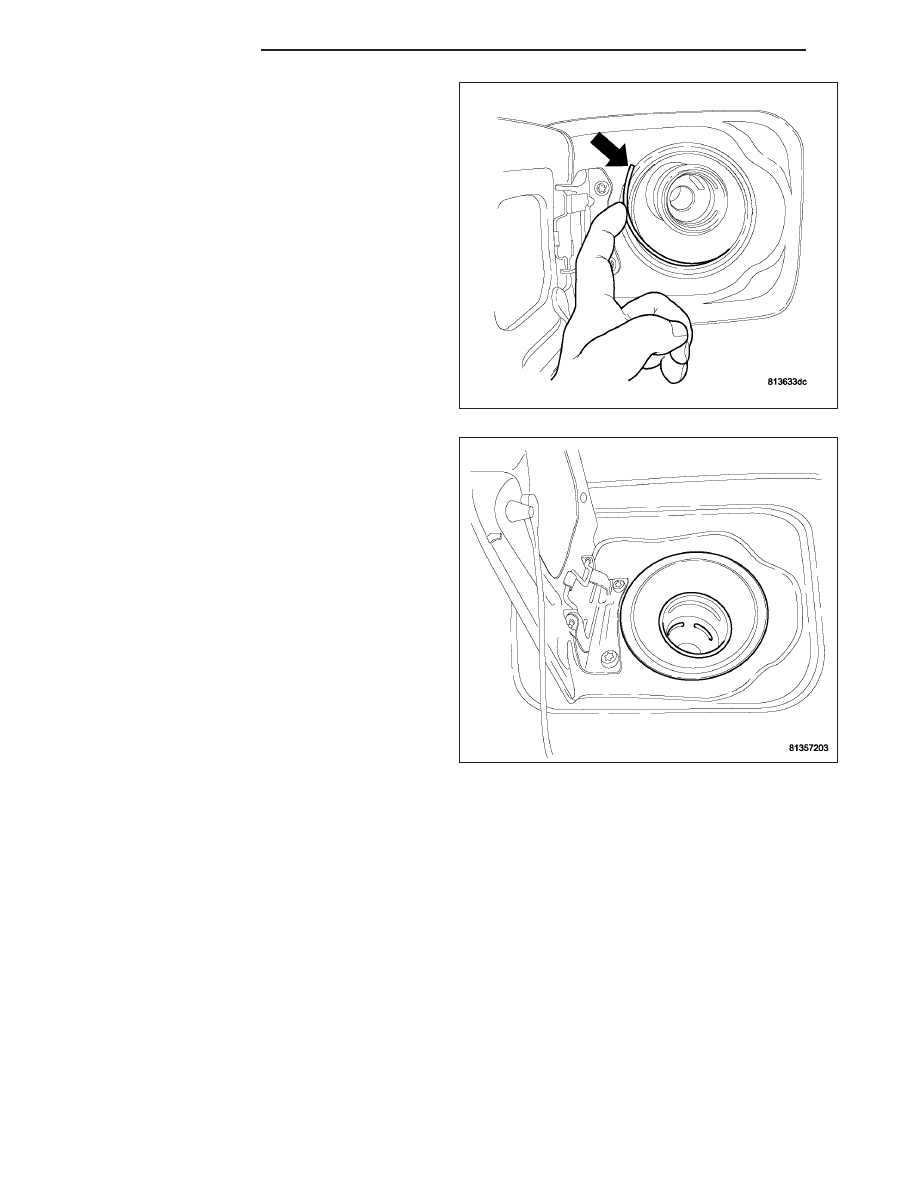
15. Work wire retaining wire around the rubber.

16. Wire retainer install.

17. Connect negative battery cable.

18. Fill fuel tank.

14 - 94

FUEL DELIVERY

LX

QUICK CONNECT FITTING

STANDARD PROCEDURE - QUICK-CONNECT FITTINGS

REMOVAL

When disconnecting a quick-connect fitting, the retainer will remain on the fuel tube nipple.

WARNING: RELEASE FUEL SYSTEM PRESSURE BEFORE DISCONNECTING A QUICK-CONNECT FITTINGS.
REFER TO THE FUEL PRESSURE RELEASE PROCEDURE. THIS MAY RESULT IN PERSONAL INJURY OR
DEATH.

1. Perform Fuel Pressure Release Procedure. Refer to the Fuel Pressure Release Procedure in this section.

2. Disconnect negative cable from battery or auxiliary jumper terminal.

3. Squeeze retainer tabs together and pull fuel tube/quick-connect fitting assembly off of fuel tube nipple. The

retainer will remain on fuel tube.

INSTALLATION

CAUTION: Make sure that the o-ring in installed in fitting. Never install a quick-connect fitting without the
retainer being either on the fuel tube or already in the quick-connect fitting. In either case, ensure the
retainer locks securely into the quick-connect fitting by firmly push-pulling-push on fuel tube and fitting to
ensure it is secured.

1. Using a clean lint free cloth, clean the fuel tube nipple and retainer.

2. Prior to connecting the fitting to the fuel tube, coat the fuel tube nipple with clean engine oil.

3. Push the quick-connect fitting over the fuel tube until the retainer seats and a click is heard.

4. The plastic quick-connect fitting has windows in the sides of the casing. When the fitting completely attaches to

the fuel tube, the retainer locking ears and the fuel tube shoulder are visible in the windows. If they are not
visible, the retainer was not properly installed. Do not rely upon the audible click to confirm a secure con-
nection.

5. Connect negative cable to battery or auxiliary

jumper terminal.

CAUTION: When using the ASD Fuel System Test,
the Auto Shutdown (ASD) Relay remains energized
for several minutes, until the test is stopped, or
until the ignition switch is turned to the Off posi-
tion.

6. Use the DRB III

T

scan tool ASD Fuel System Test

to pressurize the fuel system. Check for leaks.

Single–Button Type Fitting

1.

This type of fitting is equipped with a single push-

button located on the quick-connect fitting. The push-button is attached to two internal latches. To disconnect,
press on button with your thumb and unlatch fitting from fuel line. Special tools are not required for disconnec-
tion. DO NOT ATTEMPT TO PRY OR PULL UP ON PUSH-BUTTON. LATCHES WILL BE BROKEN.

LX

FUEL DELIVERY

14 - 95

TWO-TAB TYPE FITTING

This type of fitting is equipped with tabs located on
both sides of the fitting. These tabs are supplied for
disconnecting the quick-connect fitting from compo-
nent being serviced.

CAUTION: The interior components (O-rings, spac-
ers) of this type of quick-connect fitting are not
serviced separately, but new plastic retainers are
available. Do not attempt to repair damaged fit-
tings or fuel lines/tubes. If repair is necessary,
replace the complete fuel tube assembly.

WARNING: THE FUEL SYSTEM IS UNDER A CON-
STANT PRESSURE (EVEN WITH THE ENGINE
OFF). BEFORE SERVICING ANY FUEL SYSTEM
HOSES, FITTINGS OR LINES, THE FUEL SYSTEM
PRESSURE MUST BE RELEASED. REFER TO THE
FUEL PRESSURE RELEASE PROCEDURE IN THIS
GROUP. THIS MAY RESULT IN PERSONAL INJURY
OR DEATH.

DISCONNECTION/CONNECTION

1. Perform fuel pressure release procedure. Refer to

Fuel Pressure Release Procedure in this group.

2. Disconnect negative battery cable from battery or

auxiliary jumper terminal.

3. Clean fitting of any foreign material before disas-

sembly.

4. To disconnect quick-connect fitting, squeeze plastic

retainer tabs against sides of quick-connect fitting
with your fingers. Tool use is not required for
removal and may damage plastic retainer. Pull fit-
ting from fuel system component being serviced.
The plastic retainer will remain on component
being serviced after fitting is disconnected. The
O-rings and spacer will remain in quick-connect fit-
ting connector body.

5. Inspect quick-connect fitting body and component

for damage. Replace as necessary.

CAUTION: When the quick-connect fitting was dis-
connected, the plastic retainer will remain on the
component being serviced. If this retainer must be
removed, very carefully release the retainer from
the component with two small screwdrivers. After
removal, inspect the retainer for cracks or any
damage.

6. Prior to connecting quick-connect fitting to compo-

nent being serviced, check condition of fitting and
component. Clean parts with a lint-free cloth. Lubri-
cate with clean engine oil.

7. Insert quick-connect fitting to component being serviced and into plastic retainer. When a connection is made, a

click will be heard.

8. Verify a locked condition by firmly push-pulling-push on fuel tube and fitting (15-30 lbs.).

14 - 96

FUEL DELIVERY

LX

9. Connect negative cable to battery or auxiliary jumper terminal.

10. Use the DRB III

T

scan tool ASD Fuel System Test to pressurize the fuel system. Check for leaks.

PLASTIC RETAINER RING TYPE FITTING

This type of fitting can be identified by the use of a full-round plastic retainer ring usually black in color.

CAUTION: The interior components (O-rings, spac-
ers, retainers) of this type of quick-connect fitting
are not serviced separately. Do not attempt to
repair damaged fittings or fuel lines/tubes. If repair
is necessary, replace the complete fuel tube
assembly.

WARNING: THE FUEL SYSTEM IS UNDER A CON-
STANT PRESSURE (EVEN WITH THE ENGINE
OFF). BEFORE SERVICING ANY FUEL SYSTEM
HOSES, FITTINGS OR LINES, THE FUEL SYSTEM
PRESSURE MUST BE RELEASED. REFER TO THE
FUEL

SYSTEM

PRESSURE

RELEASE

PROCE-

DURE IN THIS GROUP. THIS MAY RESULT IN PER-
SONAL INJURY OR DEATH.

DISCONNECTION/CONNECTION

1. Perform fuel pressure release procedure. Refer to

Fuel Pressure Release Procedure in this section.

2. Disconnect negative battery cable from battery or

auxiliary jumper terminal.

3. Clean fitting of any foreign material before disassembly.

4. To release fuel system component from quick-connect fitting, firmly push fitting towards component being ser-

viced while firmly pushing plastic retainer ring into fitting. With plastic ring depressed, pull fitting from component.
The plastic retainer ring must be pressed squarely into fitting body. If this retainer is cocked during
removal, it may be difficult to disconnect fitting. Use an open-end wrench on shoulder of plastic retainer
ring to aid in disconnection.

5. After disconnection, plastic retainer ring will remain with quick-connect fitting connector body.

6. Inspect fitting connector body, plastic retainer ring and fuel system component for damage. Replace as neces-

sary.

7. Prior to connecting quick-connect fitting to component being serviced, check condition of fitting and component.

Clean parts with a lint-free cloth. Lubricate with clean engine oil.

8. Insert quick-connect fitting into component being serviced until a click is felt.

9. Verify a locked condition by firmly push-pulling-push on fuel tube and fitting (15-30 lbs.).

10. Connect negative battery cable to battery or auxiliary jumper terminal.

11. Use the DRB III

T

scan tool ASD Fuel System Test to pressurize the fuel system. Check for leaks.

LX

FUEL DELIVERY

14 - 97


Content   ..  1753  1754  1755  1756   ..