Chrysler 300/300 Touring/300C, Dodge Magnum. Manual - part 1714


  Index      Chrysler     Chrysler 300/300 Touring/300C, Dodge Magnum - service repair manual


Search            


Content   ..  1712  1713  1714  1715   ..


Chrysler 300/300 Touring/300C, Dodge Magnum. Manual - part 1714


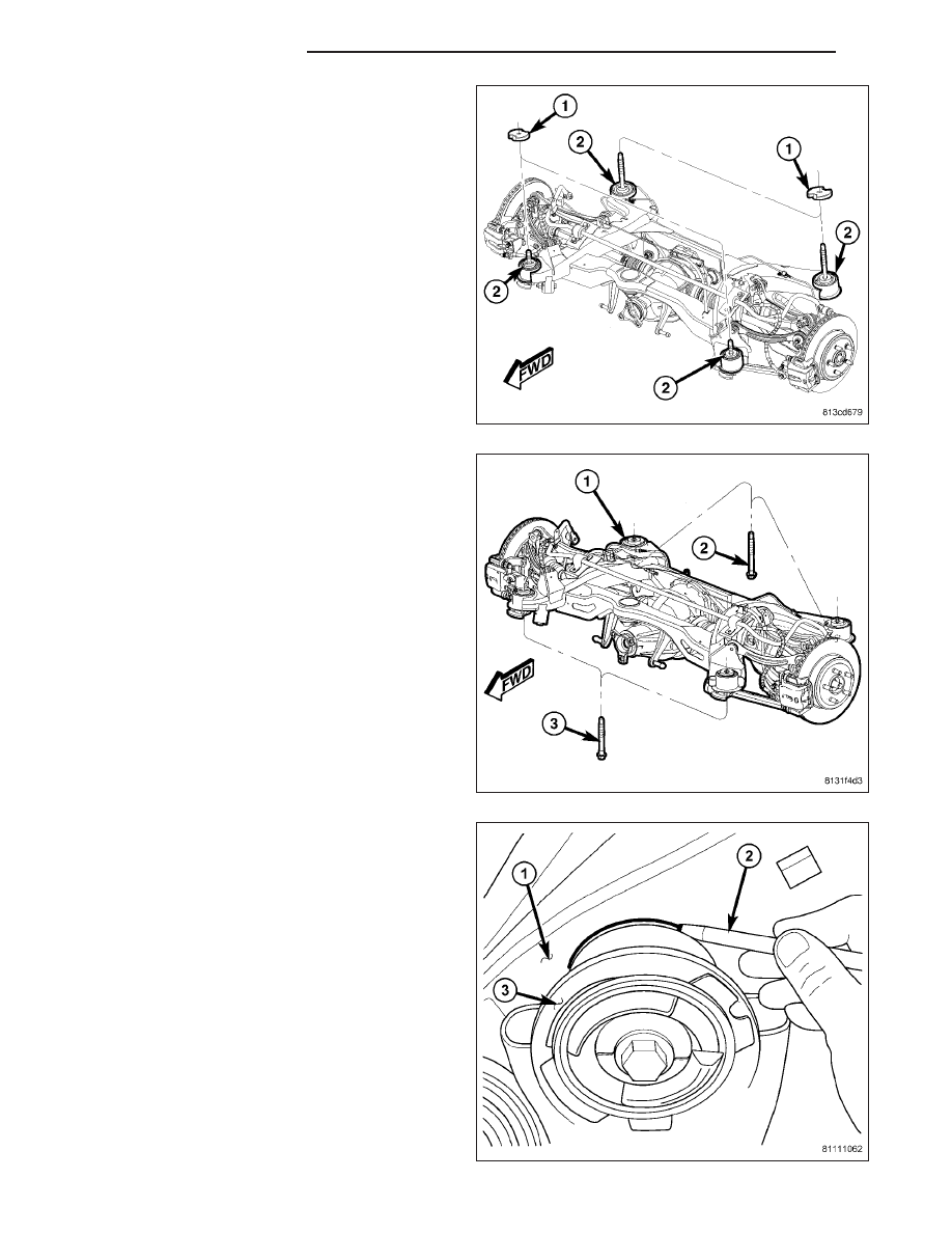
20. If vehicle is equipped with AWD, insert spacers (1)

on top of left crossmember mount bushings (2)
before crossmember is raised into place.

NOTE: There are four crossmember mounting
bolts. Rear mounting bolts (2) are longer than
front mounting bolts (3). Do not interchange
mounting bolts.

21. Raise left side of crossmember (1) into mounted

position. Install left side crossmember mounting
bolts (2 and 3). Snug, but do not fully tighten
bolts at this time.

22. Shift crossmember as necessary to line up

mounts (3) with location marks drawn on body (1)
before removal.

13 - 56

FRAME & BUMPERS

LX

23. Once mounts are lined up with location marks, on

both sides of vehicle, measure distance (1)
between the tension link (2) and weld flange (3)
on body directly in front of it, just outboard of the
front mount bushing (4). This distance must be
at least 12 mm to allow proper clearance for
suspension movement. 
If distance is less than
12 mm on either side of vehicle, shift that side of
rear crossmember directly rearward until distance
is 12 mm or greater. To do so, loosen 3 mounting
bolts slightly, leaving one on opposite side of shift
snugged to pivot off of. Shift crossmember rear-
ward and snug loosened bolts. Remeasure oppo-
site side to be sure it still maintains minimum 12
mm distance.

24. Tighten all four crossmember mounting bolts (2

and 3) to 180 N·m (133 ft. lbs.).

25. Remove jack (3) from under rear axle differential.

LX

FRAME & BUMPERS

13 - 57

26. Remove bungee cord (1) supporting propeller

shaft (2).

27. Align propeller shaft index marks (3) placed upon

removal. Install propeller shaft rear coupler-to-axle
flange bolts and nuts by hand. Tighten propeller
shaft rear coupler-to-axle flange bolts to 81 N·m
(60 ft. lbs.).

28. Install fuel filler tube. (Refer to 14 - FUEL SYS-

TEM/FUEL DELIVERY/FUEL TANK FILLER TUBE
- INSTALLATION)

13 - 58

FRAME & BUMPERS

LX

29. Clip left rear wheel speed sensor cable (3) to

routing clip (1) near body connector.

30. Match left rear wheel speed sensor connector (4)

to right sensor connector (3) to make one connec-
tor.

31. Insert speed sensor connectors (3 and 4) into

body wiring harness connector (1) located in lug-
gage compartment floor pan (2). When installing
connector, make sure retaining clip on body con-
nector is properly in place and sensor connector
cannot be pulled out.

32. If equipped with standard or premium disc brakes,

on each rear disc brake:

a. Push caliper guide pins into caliper adapter to

clear caliper mounting bosses when installing.

b. Guide caliper and brake hose down through

rear suspension, then slide caliper over brake
pads and onto caliper adapter (3).

c.

CAUTION: Extreme caution should be taken not to
cross-thread caliper guide pin bolts (2) when they
are installed.Align caliper mounting holes with
guide pins, then install guide pin bolts (2). While
holding guide pins from turning, tighten bolts to
31 N·m (23 ft. lbs.) torque.

d. Make sure brake hose is properly routed and

will not come in contact with suspension
components.

LX

FRAME & BUMPERS

13 - 59


Content   ..  1712  1713  1714  1715   ..