Chrysler 300/300 Touring/300C, Dodge Magnum. Manual - part 1709


  Index      Chrysler     Chrysler 300/300 Touring/300C, Dodge Magnum - service repair manual


Search            


Content   ..  1707  1708  1709  1710   ..


Chrysler 300/300 Touring/300C, Dodge Magnum. Manual - part 1709


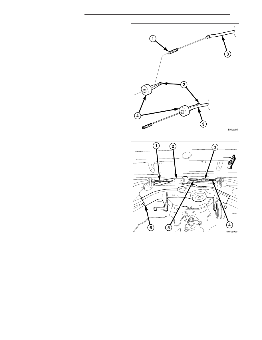
35. Route parking brake cable above rear crossmem-

ber, then slide cable (1, 3) through equalizer (2)
above rear axle differential (once installed).

NOTE: Due to short travel and low spring tension,
it is not necessary to lock-out parking brake lever
to service parking brake components.

36. Connect front parking brake cable (5) at connec-

tor (3) to right rear parking brake cable (4).

13 - 36

FRAME & BUMPERS

LX

37. Insert front parking brake cable routing bracket

locating pin into front flange of crossmember (3),
then install screw (2) fastening cable (1) routing
bracket to rear crossmember.

38. On each side of vehicle, slide an axle half shaft

(2) through hub and bearing and install hub nut
(1). Do not tighten hub nuts at this time.

39. Install rear axle differential. (Refer to 3 - DIFFER-

ENTIAL & DRIVELINE/REAR AXLE - 198 MM -
INSTALLATION) (Refer to 3 - DIFFERENTIAL &
DRIVELINE/REAR AXLE - 210 MM - INSTALLA-
TION) (Refer to 3 - DIFFERENTIAL & DRIV-
ELINE/REAR AXLE - 215RII - INSTALLATION)

40. While a helper applies brakes to keep hub from

turning, tighten hub nut to 213 N·m (157 ft. lbs.).

LX

FRAME & BUMPERS

13 - 37

41. Install

rear

exhaust

system

(2)

(dual-outlet

exhaust shown in figure). (Refer to 11 - EXHAUST
SYSTEM - INSTALLATION)

42. Install tire and wheel assemblies (1). Tighten

wheel mounting nuts (3) to 150 N·m (110 ft. lbs.).
(Refer to 22 - TIRES/WHEELS - INSTALLATION)

43. Lower vehicle.

44. Connect battery negative cable (2) to battery post.

It is important that this is performed properly.
(Refer to 8 - ELECTRICAL/BATTERY SYSTEM -
STANDARD PROCEDURE)

45. Pump brake pedal several times to ensure vehicle

has a firm brake pedal before moving vehicle.

46. Position vehicle on alignment rack/drive-on lift.

Raise vehicle as necessary to access mounting
bolts.

13 - 38

FRAME & BUMPERS

LX

47. Tighten shock absorber lower mounting bolt nuts

(4) to 72 N·m (53 ft. lbs.).

48. Perform wheel alignment, paying special attention

to thrust angle. If rear crossmember needs to be
shifted to align thrust angle, try to avoid compro-
mising tension link clearance (Refer to Step 23).
(Refer to 2 - SUSPENSION/WHEEL ALIGNMENT
- STANDARD PROCEDURE)

LX

FRAME & BUMPERS

13 - 39


Content   ..  1707  1708  1709  1710   ..