Chrysler 300/300 Touring/300C, Dodge Magnum. Manual - part 170


  Index      Chrysler     Chrysler 300/300 Touring/300C, Dodge Magnum - service repair manual


Search            


Content   ..  168  169  170  171   ..


Chrysler 300/300 Touring/300C, Dodge Magnum. Manual - part 170


4. Install and adjust brake lamp switch (2). (Refer to 8

- ELECTRICAL/LAMPS/LIGHTING - EXTERIOR/
BRAKE LAMP SWITCH - INSTALLATION)

5. Install steering column opening cover. (Refer to 23 - BODY/INSTRUMENT PANEL/STEERING COLUMN OPEN-

ING COVER - INSTALLATION)

6. Install driver side silencer under instrument panel. (Refer to 23 - BODY/INSTRUMENT PANEL/INSTRUMENT

PANEL SILENCER - INSTALLATION)

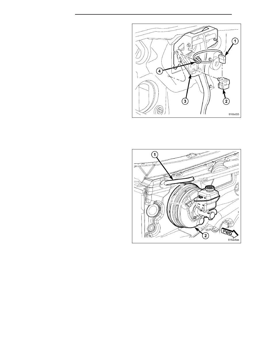
7. Connect vacuum hose (1) to check valve on face

of booster (2). Do not remove check valve from
booster.

5 - 122

BRAKES - BASE

LX

CAUTION: When replacing master cylinder on
vehicle, a NEW vacuum seal (2) MUST be installed
on master cylinder.

8. Install NEW vacuum seal (1) on rear of master cyl-

inder (2) making sure seal fits squarely in mounting
groove.

9. Position master cylinder (3) on studs of power

brake booster, aligning booster push rod with mas-
ter cylinder piston.

10. Install two master cylinder mounting nuts (1).

Tighten mounting nuts to 15 N·m (133 in. lbs.).

11. Thread primary (3) and secondary (2) brake tubes

into master cylinder primary and secondary ports.
Tighten tube nuts to 20 N·m (177 in. lbs.).

LX

BRAKES - BASE

5 - 123

12. Connect wiring harness connector (4) to brake

fluid level sensor (2) mounted in brake fluid reser-
voir (1).

13. Install windshield wiper module and components removed to access. (Refer to 8 - ELECTRICAL/WIPERS/

WASHERS/WIPER MODULE - INSTALLATION)

14. Connect battery negative cable (2) to battery post.

It is important that this is performed properly.
(Refer to 8 - ELECTRICAL/BATTERY SYSTEM -
STANDARD PROCEDURE)

15. Fill and bleed brakes as necessary.

16. Road test vehicle to ensure proper operation of

brakes.

5 - 124

BRAKES - BASE

LX

VALVE - PROPORTIONING

DESCRIPTION

A proportioning valve is used on each vehicle without antilock brakes. One valve is used for both rear brake hydrau-
lic circuits. The proportioning valve is located in the junction block (Refer to 5 - BRAKES - BASE/HYDRAULIC/
MECHANICAL/JUNCTION BLOCK - DESCRIPTION). The valve is not serviceable and must be replaced as part of
the junction block.

OPERATION

Proportioning valves balance front to rear braking by controlling (at a given ratio) brake hydraulic pressure to the
rear brakes above a preset level (split point). On light pedal applications equal brake pressure is transmitted to both
the front and rear brakes. On heavier pedal applications, through the use of proportioning valves, the pressure
transmitted to the rear will be lower than the front brakes. This prevents premature rear wheel skid.

LX

BRAKES - BASE

5 - 125


Content   ..  168  169  170  171   ..