Chrysler 300/300 Touring/300C, Dodge Magnum. Manual - part 1563


  Index      Chrysler     Chrysler 300/300 Touring/300C, Dodge Magnum - service repair manual


Search            


Content   ..  1561  1562  1563  1564   ..


Chrysler 300/300 Touring/300C, Dodge Magnum. Manual - part 1563


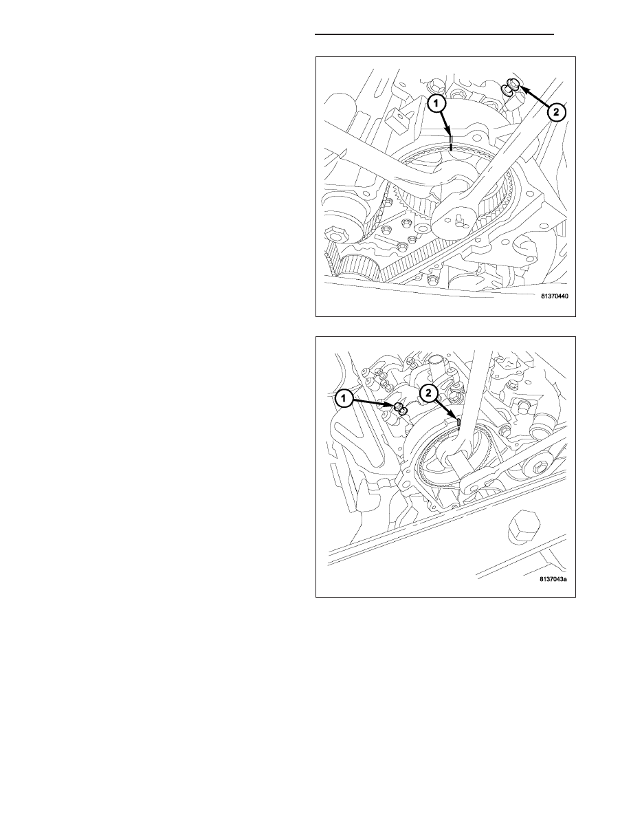
9. Hold left camshaft sprocket with a 36 mm (1 7/16

in.) box end wrench.

10. Loosen and remove the camshaft gear retaining

bolt and washer. The left bolt is 255 mm (10.0 in.)
long.

NOTE: The camshaft timing gears are keyed to the
camshaft.

11. Remove the camshaft sprocket.

CAUTION: The right camshaft must be pushed
rearward approximately 3 1/2 inches to remove the
camshaft gear retaining bolt and gear. Care must
be taken not to scratch or nick the camshaft or
cylinder head journals when moving camshaft.

12. Hold right camshaft sprocket with a 36 mm (1

7/16 in.) box end wrench.

13. Loosen and remove the camshaft gear retaining

bolt and washer. The right bolt is 213 mm (8 3/8
in.) long.

NOTE: The camshaft timing gears are keyed to the
camshaft.

14. Remove the camshaft sprocket.

9 - 2276

ENGINE - 3.5L - SERVICE INFORMATION

LX

CRANKSHAFT SPROCKET

1. Remove the timing belt (Refer to 9 - ENGINE/

VALVE

TIMING/TIMING

BELT/CHAIN

AND

SPROCKETS - REMOVAL).

2. Remove crankshaft sprocket using Special Tool

L-4407-A (1).

INSPECTION

TIMING BELT

1. Remove front timing belt cover (Refer to 9 -

ENGINE/VALVE TIMING/TIMING BELT / CHAIN
COVER(S) - REMOVAL).

2. Inspect both sides of the timing belt. Replace belt if

any of the following conditions exist :

a. Hardening of back rubber back side is glossy

without resilience and leaves no indent when
pressed with fingernail.

b. Cracks (4) on rubber back.

c. Cracks or peeling (1) of canvas.

d. Cracks on rib root.

e. Cracks on belt sides.

f. Missing teeth (2).

g. Abnormal wear (7) of belt sides. The sides are

normal if they are sharp as if cut by a knife.

h. Vehicle mileage or time at component mainte-

nance requirement. (Refer to LUBRICATION &
MAINTENANCE/MAINTENANCE SCHEDULES
- DESCRIPTION)

3. If none of the above conditions are seen on the belt, the front timing belt cover can be installed (Refer to 9 -

ENGINE/VALVE TIMING/TIMING BELT / CHAIN COVER(S) - INSTALLATION).

LX

ENGINE - 3.5L - SERVICE INFORMATION

9 - 2277

TIMING VERIFICATION

Remove the outer timing covers. Rotate the crankshaft until the pointer on the crankshaft sprocket (10) aligns the
TDC mark on the oil pump (9). Check to determine if the camshaft sprocket (2, 7) timing marks (1, 8) are aligned
with the marks on the inner timing cover. It may take an additional full revolution of the crankshaft before the cam-
shaft sprocket marks are aligned.

INSTALLATION

TIMING BELT

CAUTION: If camshafts have moved from the timing marks, always rotate camshaft towards the direction
nearest to the timing marks (DO NOT TURN CAMSHAFTS A FULL REVOLUTION OR DAMAGE to valves
and/or pistons could result).

TIMING GEAR ALIGNMENT

1 - RIGHT CAMSHAFT GEAR ALIGNMENT MARK

7 - LEFT CAMSHAFT GEAR

2 - RIGHT CAMSHAFT GEAR

8 - LEFT CAMSHAFT GEAR ALIGNMENT MARK

3 - CYLINDER HEAD TO INNER TIMING BELT COVER BOLTS -
RIGHT

9 - CRANKSHAFT GEAR ALIGNMENT MARK

4 - TIMING BELT

10 - CRANKSHAFT GEAR

5 - WATER PUMP PULLEY

11 - TIMING BELT TENSIONER PULLEY

6 - CYLINDER HEAD TO INNER TIMING BELT COVER BOLTS -
LEFT

12 - TIMING BELT TENSIONER

9 - 2278

ENGINE - 3.5L - SERVICE INFORMATION

LX

1. Align the crankshaft sprocket (10) with the TDC mark (9) on oil pump cover.

2. Align the camshaft sprockets (2, 7) timing reference marks (1, 8) with the marks on the rear cover.

3. Install the timing belt starting at the crankshaft sprocket (10) going in a counterclockwise direction. Install the belt

around the last sprocket. Maintain tension on the belt as it is positioned around the tensioner pulley (11).

NOTE: If the camshaft gears have been removed it is only necessary to have the camshaft gear retaining
bolts installed to a snug torque at this time.

4.

Holding the tensioner pulley (11) against the belt, install the tensioner into the housing and tighten to 28 N·m

(250 in. lbs.). Each camshaft sprocket mark should remain aligned the cover marks.

5.

When tensioner is in place pull retaining pin to allow the tensioner to extend to the pulley bracket.

6. Rotate crankshaft sprocket 2 revolutions and check the timing marks on the camshafts and crankshaft. The

marks should line up within their respective locations. If marks do not line up, repeat procedure.

NOTE: If camshaft gears have been removed and timing is correct, counterhold and tighten the camshaft
gears to final torque specification (Refer to 9 - ENGINE/VALVE TIMING/TIMING BELT/CHAIN AND SPROCK-
ETS - INSTALLATION).

7. Install the front timing belt cover (Refer to 9 - ENGINE/VALVE TIMING/TIMING BELT / CHAIN COVER(S) -

INSTALLATION).

8. Tighten the rocker arm assemblies and install the cylinder head covers (Refer to 9 - ENGINE/CYLINDER HEAD/

ROCKER ARM / ADJUSTER ASSY - INSTALLATION).

9. Connect negative battery cable.

TIMING GEAR ALIGNMENT

1 - RIGHT CAMSHAFT GEAR ALIGNMENT MARK

7 - LEFT CAMSHAFT GEAR

2 - RIGHT CAMSHAFT GEAR

8 - LEFT CAMSHAFT GEAR ALIGNMENT MARK

3 - CYLINDER HEAD TO INNER TIMING BELT COVER BOLTS -
RIGHT

9 - CRANKSHAFT GEAR ALIGNMENT MARK

4 - TIMING BELT

10 - CRANKSHAFT GEAR

5 - WATER PUMP PULLEY

11 - TIMING BELT TENSIONER PULLEY

6 - CYLINDER HEAD TO INNER TIMING BELT COVER BOLTS -
LEFT

12 - TIMING BELT TENSIONER

LX

ENGINE - 3.5L - SERVICE INFORMATION

9 - 2279


Content   ..  1561  1562  1563  1564   ..