Chrysler 300/300 Touring/300C, Dodge Magnum. Manual - part 1562


  Index      Chrysler     Chrysler 300/300 Touring/300C, Dodge Magnum - service repair manual


Search            


Content   ..  1560  1561  1562  1563   ..


Chrysler 300/300 Touring/300C, Dodge Magnum. Manual - part 1562


COVER-REAR TIMING BELT

REMOVAL

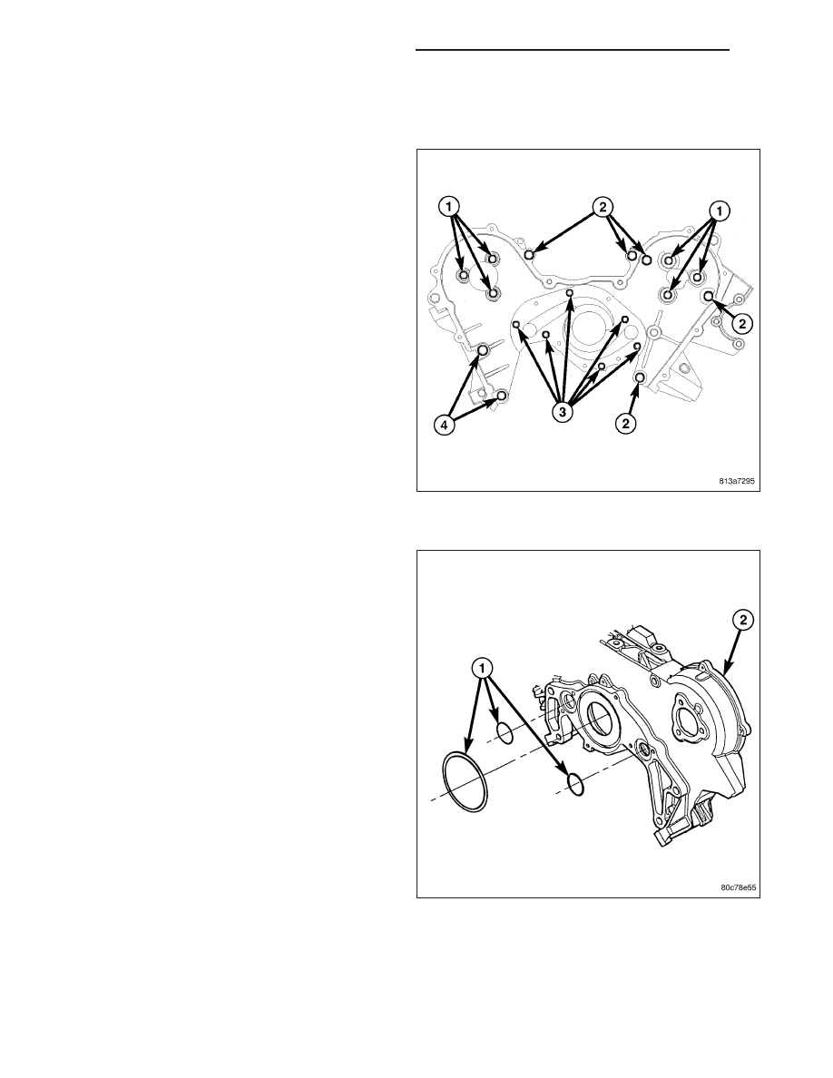
NOTE: The rear timing belt cover has O-rings to
seal the water pump passages to cylinder block.
Do not reuse the O-rings.

1. Perform fuel pressure release procedure. (Refer to

14 - FUEL SYSTEM/FUEL DELIVERY - STAN-
DARD PROCEDURE).

2. Disconnect the negative battery cable.

3. Remove timing belt (Refer to 9 - ENGINE/VALVE

TIMING/TIMING BELT/CHAIN AND SPROCKETS -
REMOVAL).

4. Remove camshaft sprockets (Refer to 9 - ENGINE/

VALVE

TIMING/TIMING

BELT/CHAIN

AND

SPROCKETS - REMOVAL).

5. Remove rear timing belt cover bolts (1, 2, 3).

6. Remove the rear cover.

INSTALLATION

1. Clean rear timing belt cover O-ring (1) sealing sur-

faces and grooves. Lubricate new O-rings with
Mopar

T

Dielectric Grease or equivalent to facilitate

assembly.

2. Position NEW O-rings on cover (2).

9 - 2272

ENGINE - 3.5L - SERVICE INFORMATION

LX

3. Install rear timing belt cover (4). Tighten bolts to

the following specified torque:

M10 (2, 5) - 54 N·m (40 ft. lbs.)

M8 (1) - 28 N·m (20 ft. lbs.)

M6 (3) - 12 N·m (105 in. lbs.)

4. Install camshaft sprockets (Refer to 9 - ENGINE/

VALVE

TIMING/TIMING

BELT/CHAIN

AND

SPROCKETS - INSTALLATION).

5. Install timing belt (Refer to 9 - ENGINE/VALVE

TIMING/TIMING BELT/CHAIN AND SPROCKETS -
INSTALLATION).

LX

ENGINE - 3.5L - SERVICE INFORMATION

9 - 2273

BELT-TIMING AND SPROCKETS

REMOVAL

TIMING BELT

CAUTION: The 3.5L is NOT a freewheeling engine. Therefore, loosen the valve train rocker assemblies
before servicing the timing drive.

1. Perform fuel pressure release procedure. (Refer to 14 - FUEL SYSTEM/FUEL DELIVERY - STANDARD PRO-

CEDURE).

2. Disconnect negative battery cable.

3. Remove both cylinder head covers and loosen the rocker arm assemblies (Refer to 9 - ENGINE/CYLINDER

HEAD/ROCKER ARM / ADJUSTER ASSY - REMOVAL).

4. Remove the front timing belt cover (Refer to 9 - ENGINE/VALVE TIMING/TIMING BELT / CHAIN COVER(S) -

REMOVAL).

5. Mark belt running direction, if timing belt is to be reused.

CAUTION: When aligning timing marks, always rotate engine by turning the crankshaft. Failure to do so will
result in valve and/or piston damage.

6. Rotate engine clockwise until crankshaft (10) mark aligns with the TDC mark on oil pump housing (9) and the

camshaft sprocket (2, 7) timing marks (1, 8) are aligned with the marks on the rear cover.

7. Remove the timing belt tensioner (12) and remove timing belt.

TIMING GEAR ALIGNMENT

1 - RIGHT CAMSHAFT GEAR ALIGNMENT MARK

7 - LEFT CAMSHAFT GEAR

2 - RIGHT CAMSHAFT GEAR

8 - LEFT CAMSHAFT GEAR ALIGNMENT MARK

3 - CYLINDER HEAD TO INNER TIMING BELT COVER BOLTS -
RIGHT

9 - CRANKSHAFT GEAR ALIGNMENT MARK

4 - TIMING BELT

10 - CRANKSHAFT GEAR

5 - WATER PUMP PULLEY

11 - TIMING BELT TENSIONER PULLEY

6 - CYLINDER HEAD TO INNER TIMING BELT COVER BOLTS -
LEFT

12 - TIMING BELT TENSIONER

9 - 2274

ENGINE - 3.5L - SERVICE INFORMATION

LX

8. Inspect the tensioner for fluid leakage.

9. Inspect the pivot and bolt for free movement, bearing grease leakage, and smooth rotation. If not rotating freely,

replace the arm and pulley assembly.

10. When tensioner is removed from the engine it is

necessary to compress the plunger into the ten-
sioner body.

CAUTION: Index the tensioner in the vise the same
way it is installed on the engine. This ensures
proper pin orientation when tensioner is installed
on the engine.

a. Place

the

tensioner into

a

vise (1) and

SLOWLY compress the plunger. Total bleed
down of tensioner should take about 5 min-
utes.

b. When plunger is compressed into the tensioner

body install a pin (2) through the body and
plunger to retain plunger in place until ten-
sioner is installed.

CAMSHAFT SPROCKETS

CAUTION: The 3.5L engine is NOT a free-wheeling
design. Therefore, care should be taken not to
rotate the camshafts or crankshaft with the timing
belt removed.

NOTE: The camshaft timing gears are keyed to the
camshaft.

1. Perform fuel pressure release procedure. (Refer to

14 - FUEL SYSTEM/FUEL DELIVERY - STAN-
DARD PROCEDURE).

2. Remove front timing belt cover (Refer to 9 -

ENGINE/VALVE TIMING/TIMING BELT / CHAIN
COVER(S) - REMOVAL).

3. Position crankshaft sprocket to the TDC mark on

the oil pump housing by turning crankshaft in the
clockwise direction.

4. Install a dial indicator in number 1 cylinder to check TDC of the piston. Rotate the crankshaft until the piston is

at exactly TDC.

5. Remove camshaft retainer/thrust plate (1) from rear of right cylinder head.

6. Remove the right cylinder head cover.

7. Remove the right rocker arm assembly.

8. Remove the timing belt tensioner and timing belt.

LX

ENGINE - 3.5L - SERVICE INFORMATION

9 - 2275


Content   ..  1560  1561  1562  1563   ..