Content .. 1538 1539 1540 1541 ..
Chrysler 300/300 Touring/300C, Dodge Magnum. Manual - part 1540
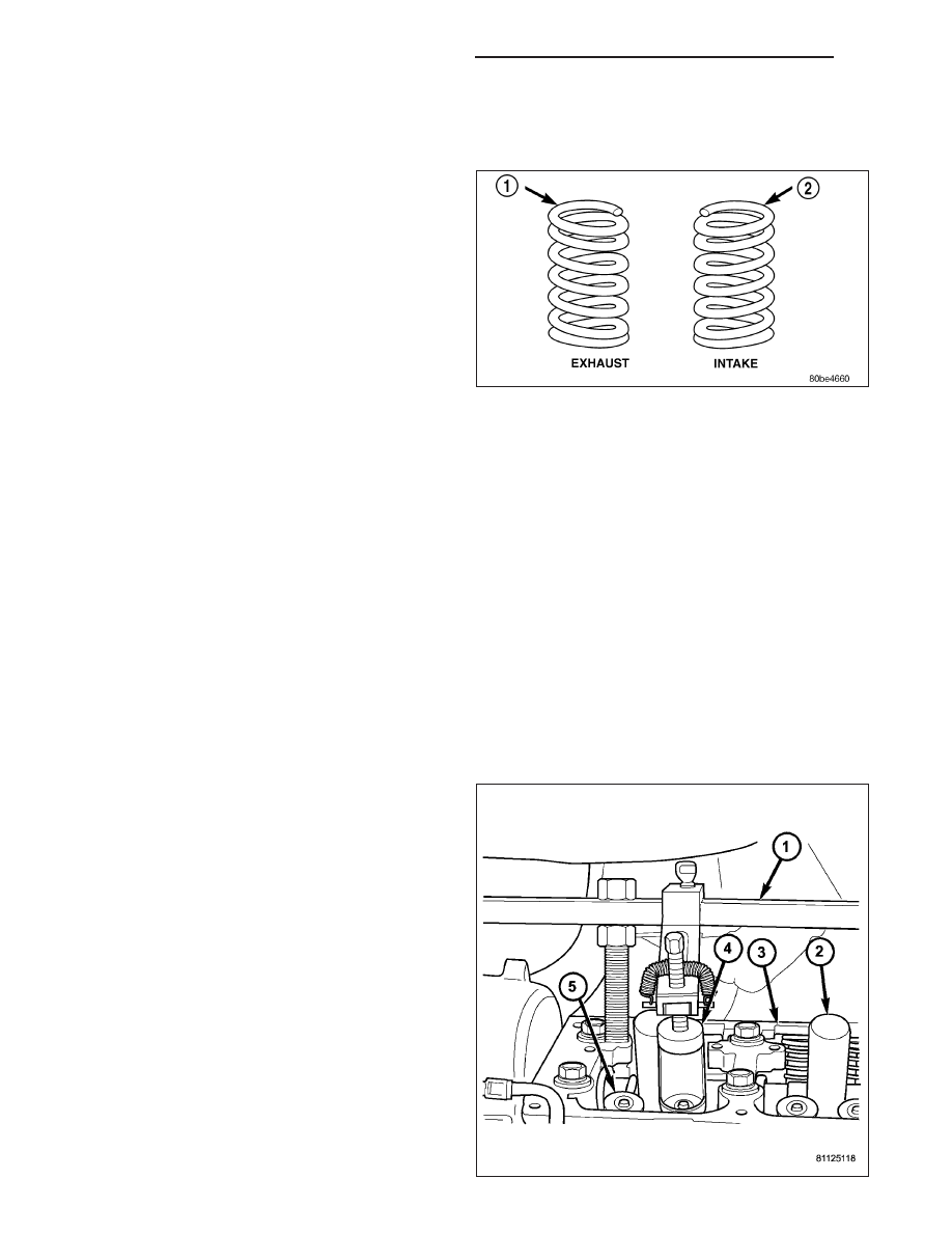
SPRING -VALVE
DESCRIPTION
The valve springs are made from chrome silicon alloy
wire and incorporate a “bee-hive” design. Valve spring
retainers and locks are common from valve-to-valve.
The valve spring seat is integral with the valve stem
oil seal, which incorporates a garter spring to maintain
consistent lubrication control to the valve stem.
The valve springs are unique for intake compared to
exhaust. Both have different lengths and are wound in
opposite directions. The valve springs are color coded,
intake spring is right hand coil direction with orange
dye on the top coils, and the exhaust spring is left
hand coil direction with a yellow or white dye on the
top coils.
The exhaust spring with the white dye on the top of the coils has an increased open and closed load when com-
pared to the exhaust spring with the yellow dye. A yellow and a white exhaust valve spring should never be used
on a single forked rocker arm. Color coated exhaust springs should always be used in pairs for a forked exhaust
rocker springs.
OPERATION
The valve spring returns the valve against its seat for a positive seal of the combustion chamber.
REMOVAL
CYLINDER HEAD OFF
1. Compress valve spring with valve spring compressor C-3422-D and adapter 6526 (Refer to 9 - ENGINE - SPE-
CIAL TOOLS).
2. Remove valve retaining locks. Release valve spring compressor. Remove valve spring retainer and valve spring.
3. Remove valve stem seal assembly. (Refer to 9 - ENGINE/CYLINDER HEAD/VALVE STEM SEALS - REMOVAL)
CYLINDER HEAD ON
1. Disconnect negative battery cable.
2. Remove upper intake manifold (Refer to 9 -
ENGINE/MANIFOLDS/INTAKE
MANIFOLD
-
REMOVAL).
3. Remove cylinder head cover(s) (Refer to 9 -
ENGINE/CYLINDER
HEAD/CYLINDER
HEAD
COVER(S) - REMOVAL).
4. Remove rocker arm and shaft assembly (Refer to 9
-
ENGINE/CYLINDER
HEAD/ROCKER
ARM
/
ADJUSTER ASSY - REMOVAL).
5. Remove spark plugs.
6. Rotate the crankshaft clockwise, until the number 1
piston is at Top Dead Center (TDC) on the com-
pression stroke.
7. With air hose attached to spark plug adapter
installed in number 1 spark plug hole, apply 620.5
to 689 kPa (90 to 100 psi) air pressure. This is to
hold valves into place while servicing components.
8. Using Tool MD 998772A (1) with adapter 6527 (4)
or equivalent, compress valve spring and remove
9 - 2184
ENGINE - 3.5L - SERVICE INFORMATION
LX