Chrysler 300/300 Touring/300C, Dodge Magnum. Manual - part 147


  Index      Chrysler     Chrysler 300/300 Touring/300C, Dodge Magnum - service repair manual


Search            


Content   ..  145  146  147  148   ..


Chrysler 300/300 Touring/300C, Dodge Magnum. Manual - part 147


CAUTION: When pushing pistons back into caliper bores, if hand pressure is not sufficient, use only a trim
stick as shown or other suitable soft tool to do so. Never use a screwdriver or other metal pry bar due to
potential damage to braking surface of rotor or pads.

6. Using hand pressure, pull pads back to seat caliper

pistons into bores if possible. If not possible, per-
form the following to do this correctly without dam-
aging the caliper, pistons, dust boots or brake rotor
disc.

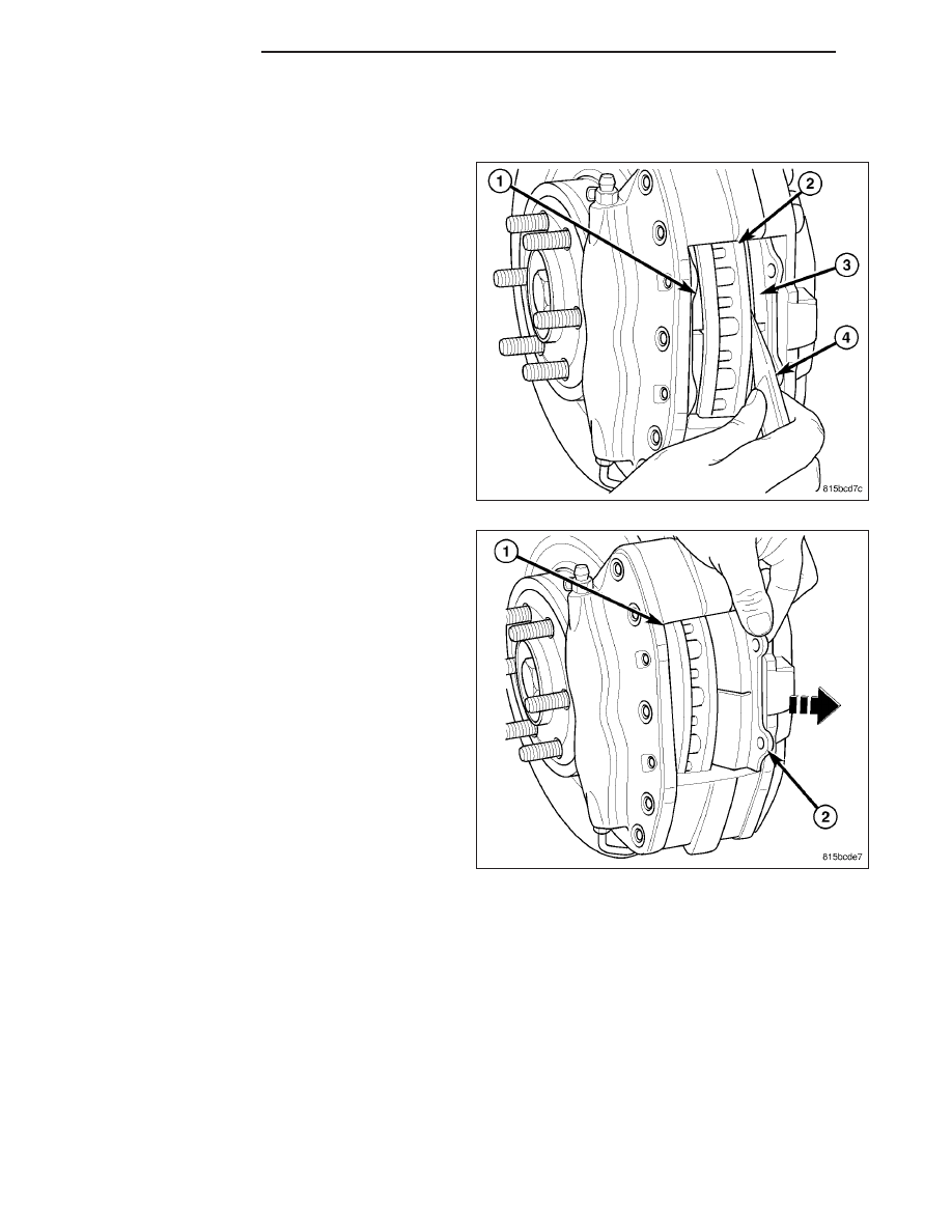
a. Place trim stick (3) between inboard brake pad

and outer edge of rotor (1).

b. Using trim stick (3), apply pressure against the

inboard brake pad until both pistons are com-
pletely bottomed in bores of inboard caliper
half. Leave trim stick in place to hold pistons in
place.

c. Place second trim stick between outboard

brake pad and rotor, then repeat above step on
outboard pad and pistons.

7. Remove inboard brake pad (2) through opening in

caliper (1). Remove outboard brake pad in same
manner.

5 - 30

BRAKES - BASE

LX

8. Once brake pads are removed from caliper (1),

inspect all four caliper pistons (3) and dust boots
(2) for evidence of brake fluid leakage. Also inspect
dust boots on all caliper pistons for any cuts, tears
or heat cracks and brake pad supports (4) (if
equipped) for excess wear or damage. If caliper
fails inspection, it should be replaced.

CLEANING

WARNING: Dust and dirt accumulating on brake parts during normal use may contain asbestos fibers from
production or aftermarket brake linings. Breathing excessive concentrations of asbestos fibers can cause
serious bodily harm. Exercise care when servicing brake parts. Do not sand or grind brake lining unless
equipment used is designed to contain the dust residue. Do not clean brake parts with compressed air or
by dry brushing. Cleaning should be done by dampening the brake components with a fine mist of water,
then wiping the brake components clean with a dampened cloth. Dispose of cloth and all residue containing
asbestos fibers in an impermeable container with the appropriate label. Follow practices prescribed by the
Occupational Safety And Health Administration (OSHA) and the Environmental Protection Agency (EPA) for
the handling, processing, and disposing of dust or debris that may contain asbestos fibers.

INSPECTION

Visually inspect brake pads for uneven lining wear. Also inspect for excessive lining deterioration. Check the clear-
ance between the tips of the wear indicators (if equipped) on the pads and the brake rotors.

If a visual inspection does not adequately determine the condition of the lining, remove the disc brake pads from the
calipers and perform a physical check.

NOTE: It is important to inspect both front and rear brake pads during the same inspection. Typically, front
and rear brake pads wear out at the same time.

When servicing, replace both disc brake pads (inboard and outboard) for each caliper. It is necessary to replace the
pads on the opposite side of the vehicle as well as the pads failing inspection.

If the brake pads do not require replacement, be sure to reinstall the brake pads in the original position they were
remove from.

INSTALLATION

NOTE: Perform Step 1 through Step 10 on each side of vehicle to complete pad set installation before pro-
ceeding with Step 11.

1. Make sure all caliper pistons are fully seated (bottomed) in bores.

LX

BRAKES - BASE

5 - 31

2. Slide NEW inboard (2) and outboard brake pads

into opening (1) in disc brake caliper. If installing
rear brake pads, make sure beveled end of
each pad lining is directed against the direction
the rotor is rotating in when vehicle is moving
forward, in other words, the rear pads need to
have beveled end facing upward.

3. From inboard side, slide upper brake pad support

pin (2) through caliper (3) and upper holes in both
brake pads (1). Ensure that small end of support
pin is in hole (4) in outboard half of caliper.

4. Install upper end of brake pad spring clip (2) under

upper brake pad support pin (1).

5 - 32

BRAKES - BASE

LX

5. Press on lower end of spring clip (5) until it touches

brake rotor.

6. Slide lower brake pad support pin (2) through cali-

per (1) and lower holes in both brake pads (3) in
the same manner the upper pin was installed.
Ensure small end of support pin is in hole (4) in
outboard half of caliper.

7. Release the spring clip allowing it to engage lower

support pin.

8. From inboard side, seat upper and lower support

pins (4) into caliper (3) using pin punch (1) and
hammer (2). Support pins must be driven into cali-
per until support pin retaining rings are locked into
place.

9. Once support pins are fully installed into caliper,

inspect assembled caliper to make sure spring clip
(2) is centered in opening (1) of caliper, correctly
engaging upper and lower support pins, and is
resting against both brake pads (3).

LX

BRAKES - BASE

5 - 33


Content   ..  145  146  147  148   ..