Content .. 1271 1272 1273 1274 ..
Chrysler 300/300 Touring/300C, Dodge Magnum. Manual - part 1273
•
When Monitored:
With the ignition on and the Fuel Pressure Solenoid command on.
•
Set Condition:
The ECM detects excessive current on the (K370) Fuel Pressure Solenoid Control circuit for 0.28 second.
Possible Causes
INTERMITTENT DTC
(K370) FUEL PRESSURE SOLENOID CONTROL CIRCUIT SHORTED TO VOLTAGE
(K370) FUEL PRESSURE SOLENOID CONTROL CIRCUIT SHORTED TO THE (K369) FUEL PRESSURE
SOLENOID 12 VOLT SUPPLY CIRCUIT
(K370) FUEL PRESSURE SOLENOID CONTROL CIRCUIT OPEN OR HIGH RESISTANCE
FUEL PRESSURE SOLENOID
ENGINE CONTROL MODULE (ECM)
Always perform the Pre-Diagnostic Troubleshooting procedure before proceeding. (Refer to 9 - ENGINE -
DIAGNOSIS AND TESTING)
Diagnostic Test
1.
DTC IS ACTIVE
Ignition on, engine not running.
With the scan tool, Clear DTCs in the Engine Control Module (ECM).
With the scan tool, actuate the Fuel Pressure Solenoid at 100%.
Monitor the scan tool for at least two minutes.
With the scan tool, select View DTCs.
Is the status Active for this DTC?
Yes
>> Go To 2
No
>> Refer to the *CHECKING FOR AN INTERMITTENT DTC Diagnostic Procedure. (Refer to 9 - ENGINE -
DIAGNOSIS AND TESTING)
2.
(K370) FUEL PRESSURE SOLENOID CONTROL CIRCUIT SHORTED TO VOLTAGE
Turn the ignition off.
Disconnect the Fuel Pressure Solenoid connector.
Disconnect the Engine Control Module (ECM) connector.
Remove the ASD Relay from the IPM.
Connect a jumper wire between cavity 30 and cavity 87 of the ASD
Relay Connector.
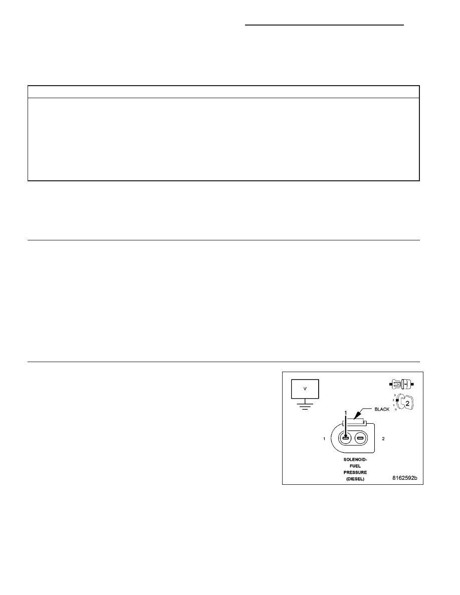
Turn the ignition on.
Measure the voltage of the (K370) Fuel Pressure Solenoid Control cir-
cuit in the Fuel Pressure Solenoid connector.
Is there any voltage present?
Yes
>> Repair the (K370) Fuel Pressure Solenoid Control circuit for
a short to voltage.
Perform the ECM Verification Test Ver. 1. (Refer to 9 - ENGINE - DIAGNOSIS AND TESTING)
No
>> Go to 3
9 - 1116
ENGINE ELECTRICAL DIAGNOSTICS - DIESEL
LX